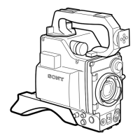
2-16
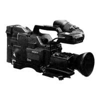
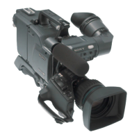
DXC-D30 (UC)
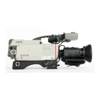
DXC-D30P (CE)
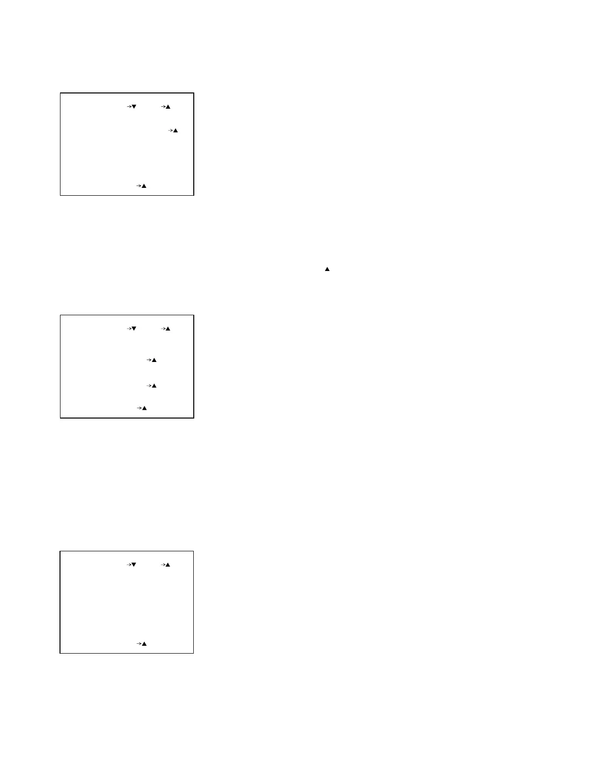
. Page 17 Various setting 4
MIC ADJ :
B :
:
ATW ADJ
R
AUTO(YES )
126
134
89
FILTER :
2
:
PAGE17(NEXT PREV )
EXIT MENU (YES )
ATW ADJ Take in standard value of ATW
R Standard value setting of ATW
B Standard value setting of ATW
MIC ADJ Setting of a musical note mark indication
FILTER Destination setting of filter (standard:2)
n: In ATW ADJ, it is taken in the calculation standard value of color
temperature when the AUTO WHITE is carried out, therefore,
normally, no adjustment is required.
When the indication value of color temperature is different from the
actual value, the CCD OUTPUT level adjustment is required, and
then, take in the standard value to the following procedures;
1. Shoot the pattern of 3200 K color temperature.
2. Set W.BAL switch to "A" position, and perform the AUTO WHITE
balance.
3. Move the cursor to "ATW ADJ" by STATUS/MENU switch, and
press UP
switch.
. Page 18 Selfdiagnosis 1
DIAG ERROR RESET
PAGE18(NEXT PREV )
EXIT MENU (YES )
(YES )
MEMORY BACKUP
(YES )
DIAG ERROR RESET
The results of error check and the history of defective item are
erased.
MEMORY BACKUP
The data of EEPROM on the TG, IF and ES boards are made backup
copy to the EEPROM on the MB board.
If the communication between the EEPROM on the TG, IF, ES
boards and microcomputer are abnormal when the power switch
turns on, the data of backup copy on the EEPROM of the MB
board is used because the data held on the EEPROM of TG, IF
and ES boards can not be used.
Therefore, make backup copy, when changing the contents of the
menu page 5 through page 8, page 11 and page 12, or when
changing the one of TG, IF, ES and MB boards.
n: The DIAG ERROR RESET and MEMORY BACKUP are carried out
when the RESET on the service menu of page 1 is executed.
. Page 19 Selfdiagnosis 2
PAGE19(NEXT PREV )
EXIT MENU (YES )
ERROR DISP 1/3
PR-G2
000H
000H
000H
:
PR-R2 :
PR-PMPD2 :
PR-PMPD1 000H
000H
:
PP-PMPD
1
:
DISP SELECT
:
DISP SELECT
The contents of the defective items are changed.
1: The result of latest error is displayed.
2: This selfdiagnosis is automatically carried out, and the defective
item diagnosed in the past are displayed.
PP-PMPD
The details of check result for the synchronization signal input and
the internal RAM in PP LSI are displayed.
800H: The internal RAM of PP LSI is abnormal.
002H: The input HD signal (PR IC405, pin102) to the PP LSI is
abnormal.
001H: The input VD signal (PR IC405, pin 101) to the PP LSI is
abnormal.
n: When the plural abnormality is occurred, the hexadecimal numbers
of three digits are displayed in the total value of each error codes.
When both HD and VD signals inputted to the PP LSI are abnormal,
the PP-PMPD is displayed in the 003H.


 To Next Page