2
HCD-BC150/BC250
General
Power requirements
North American and Mexican models:
120 V AC, 60 Hz
Taiwan model: 120V AC, 50/60 Hz
Other models: 220 − 240 V AC, 50/60 Hz
Power consumption 100 W
0.3 W (at the Power Saving
Mode)
Dimensions (approx.) 430 × 90 × 403 mm
(17 × 3
5
/
8
× 15
7
/
8
inches)
(w/h/d) incl. projecting
parts incl. projecting parts
Mass (approx.) 5.5 kg (12 lb 3 oz)
Design and specifications are subject to change
without notice.
Video section
Outputs Video: 1 Vp-p 75 ohms
S video:
Y: 1 Vp-p 75 ohms
C: 0.286 Vp-p 75 ohms
COMPONENT:
Y: 1 Vp-p 75 ohms
P
B
/C
B
, P
R
/C
R
: 0.7 Vp-p
75 ohms
North American models: 531 − 1,710 kHz (with the
interval set at 9 kHz)
530 − 1,710 kHz (with the
interval set at 10 kHz)
Middle Easten models: 531 − 1,602 kHz (with the
interval set at 9 kHz)
Other models: 531 − 1,602 kHz (with the
interval set at 9 kHz)
530 − 1,710 kHz (with the
interval set at 10 kHz)
antenna AM loop antenna
Intermediate frequency 450 kHz
AM tuner section
Tuning range
TABLE OF CONTENTS
1. GENERAL ................................................................... 4
2. DIAGRAMS
2-1. Printed Wiring Board — RF Section — .......................... 7
2-2. Schematic Diagram — RF Section — ............................ 8
2-3. Printed Wiring Board — CD Mechanism Section — ..... 9
2-4. Schematic Diagram — CD Mechanism Section — ........ 10
2-5. Printed Wiring Board — DMB07 Section (Side A) — ... 11
2-6. Printed Wiring Board — DMB07 Section (Side B) — ... 12
2-7. Schematic Diagram — DMB07 Section (1/8) — .......... 13
2-8. Schematic Diagram — DMB07 Section (2/8) — .......... 14
2-9. Schematic Diagram — DMB07 Section (3/8) — .......... 15
2-10. Schematic Diagram — DMB07 Section (4/8) — .......... 16
2-11. Schematic Diagram — DMB07 Section (5/8) — .......... 17
2-12. Schematic Diagram — DMB07 Section (6/8) — .......... 18
2-13. Schematic Diagram — DMB07 Section (7/8) — .......... 19
2-14. Schematic Diagram — DMB07 Section (8/8) — .......... 20
2-15. Printed Wiring Board — MAIN Section (Side A) — .... 21
2-16. Printed Wiring Board — MAIN Section (Side B) — ..... 22
2-17. Schematic Diagram — MAIN Section (1/2) — .............. 23
2-18. Schematic Diagram — MAIN Section (2/2) — .............. 24
2-19. Printed Wiring Board — PANEL/FL/POWER SW/
H/P/AMP RETAINER Section —................................... 25
2-20. Schematic Diagram — PANEL/FL/POWER SW/
H/P/AMP RETAINER Section —................................... 26
2-21. Printed Wiring Board — IO Section — .......................... 27
2-22. Schematic Diagram — IO Section — ............................. 28
2-23. Printed Wiring Board — AMP Section (Side A) —........ 29
2-24. Printed Wiring Board — AMP Section (Side B) — ....... 30
2-25. Schematic Diagram — AMP Section (1/4) — ............... 31
2-26. Schematic Diagram — AMP Section (2/4) — ............... 32
2-27. Schematic Diagram — AMP Section (3/4) — ............... 33
2-28. Schematic Diagram — AMP Section (4/4) — ............... 34
2-29. Printed Wiring Board — SPK/LF Section — ................. 35
2-30. Schematic Diagram — SPK/LF Section — .................... 35
3. EXPLODED VIEWS
3-1. Overall Section ................................................................ 59
3-2. Front Panel Section ......................................................... 60
3-3. Chassis Section-1 ............................................................ 61
3-4. Chassis Section-2 ............................................................ 62
3-5. CD Mechanism Section-1
(CDM81A-DVBU27) ...................................................... 63
3-6. CD Mechanism Section-2
(CDM81A-DVBU27) ...................................................... 64
3-7. CD Mechanism Section-3
(CDM81A-DVBU27) ...................................................... 65
3-8. Base Unit Section (DVBU27) ......................................... 66
4. ELECTRICAL PARTS LIST .................................. 67
Ver 1.3
Y
P
B
/C
B
P
R
/C
R
S
VIDEO
VIDEO
(
DVD O NLY
)
AUDIO IN
FRONT R
SURR R SURR LWOOFER
CENTER FRONT L
L
R
MONITOR OUT
COMPONENT VIDEO OUT
VIDEO/SAT
SPEAKER
COAXIAL
AM
FM
75
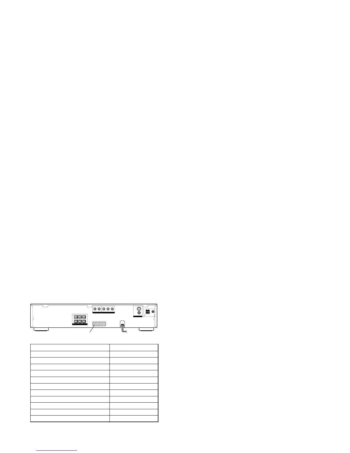
Part No.
MODEL IDENTIFICATION
– Rear Panel –
Model Part No.
HCD-BC150 KR 2-177-675-0[]
HCD-BC150 US 4-252-115-0[]
HCD-BC150 CND 4-252-115-1[]
HCD-BC150 EA 4-252-115-2[]
HCD-BC150 AUS 4-252-115-3[]
HCD-BC150 E41 4-252-115-4[]
HCD-BC150 MX 4-252-115-5[]
HCD-BC250 US 4-252-115-6[]
HCD-BC250 CND 4-252-115-7[]
HCD-BC250 MX 4-252-115-8[]
HCD-BC150 TW 4-252-115-9[]
•Abbreviation
AUS: Australian model.
CND : Canadian model.
E41 : 230 V AC Area in E model.
EA : Saudi Arabia model.
KR : Korea model.
MX : Mexican model.
TW : Taiwan model.