15
HCD-DZ3K
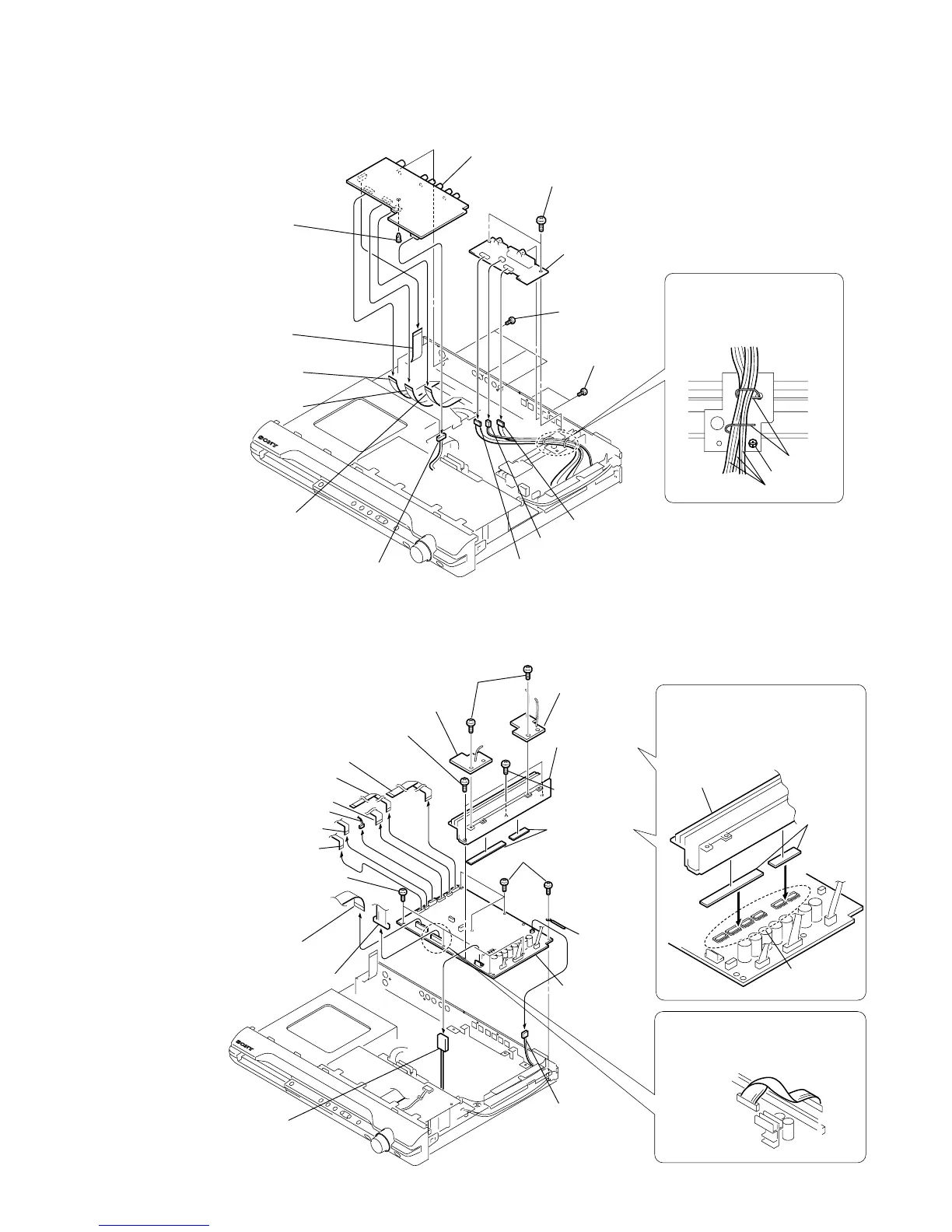
3-6. MAIN BOARD
3-5. I/O BOARD
4
wire (flat type)
13core (CN201)
8
I/O board
7
PWB support
qf
SPEAKER board
qd
two screws (+BV 3
×
6)
6
three screws
(+BVTP 3
×
8)
9
connector (CN303)
q;
connector (CN302)
5
wire (flat type)
9core (CN203)
1
connector
(CN312)
3
wire (flat type)
13core (CN311)
2
wire (flat type)
7core (CN202)
qs
two screws
(+BVTP 3
×
8)
qa
connector (CN301)
screw
lead pin
When assembling,
clamp the three harnesses with
a lead pin or a similar tool so
that they do not touch this screw.
three harnesses
q;
connector
(CN3000)
7
wire (flat type)
23core (CN509)
5
wire (flat type) 5core (CN1202)
3
wire (flat type) 24core (CN1101)
2
wire (flat type) 7core (CN1302)
1
wire (flat type) 13core (CN1301)
qa
two screws
(+BV 3
×
8)
ql
four screws (+BV 3
×
6)
wa
MAIN board
qk
four screws (+BV 3
×
6)
8
connector (CN515)
4
connector (CN1201)
w;
clamp
When re-assembling, attaching the
two heat radiation sheets on the
IC MAIN board first, and then attach
the heat sink (AMP).
heat sink (AMP)
radiation
sheets
IC on the
MAIN board
qd
HEATSINK
B board
qh
heat sink (AMP)
qs
HEATSINK A board
qg
screw
(+BVTP 3
×
12)
qj
two radiation
sheets
6
wire (flat type) 13core (CN507)
9
connector
(CN3002)
qf
two screws
(+BV 3
×
10)
After twist the harness once,
install the connector.
POWER board
MAIN board
 Loading...