18
HCD-TB10
CN731
TP731:
TP connected to pin
q;
(IC751)
IC751
CN733
IC731
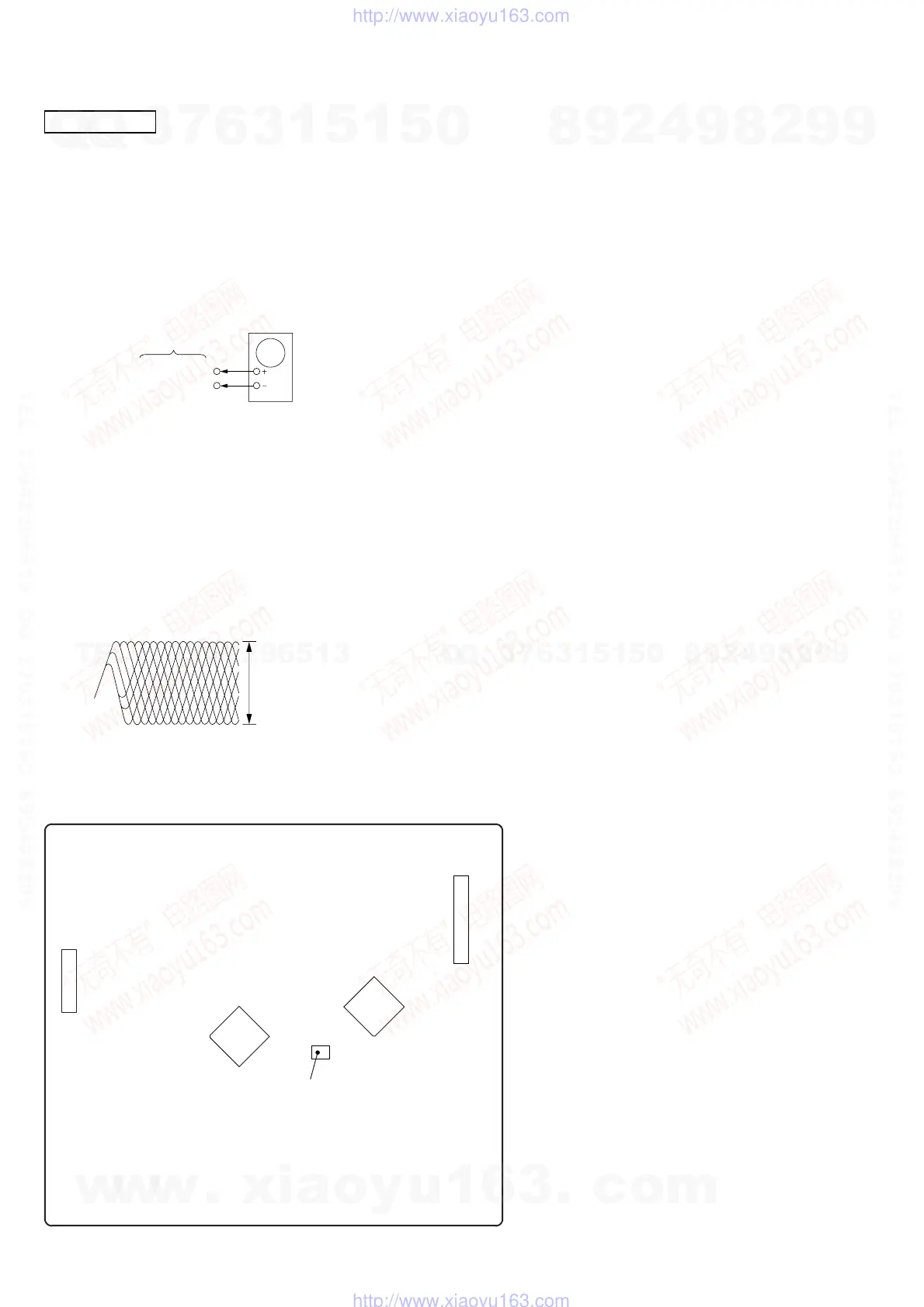
Adjustment Location: CDM board
[CDM BOARD] (Component Side)
CD SECTION
RF Level Check
Procedure :
1. Connect oscilloscope to pin q; (IC751).
2. Turn the set on.
3. Load a disc (YEDS-18) and play the number five track.
4. Confirm that oscilloscope waveform is clear and check RF signal
level is correct or not.
IC751 pin q;
GND
CDM board
oscilloscope
Note : Clear RF signal waveform means that the shape “ ◊ ” can be clearly
distinguished at the center of the waveform.
RF signal waveform
VOLT/DIV : 200mV
TIME/DIV : 500ns
level : 1.4 to 2.1 Vp-
Note :
1. CD Block is basically designed to operate without adjustment.
Therefore, check each item in order given.
2. Use YEDS-18 disc (3-702-101-01) unless otherwise indicated.
3. Use an oscilloscope with more than 10MΩ impedance.
4. Clean the object lens by an applicator with neutral detergent
when the signal level is low than specified value with the
following checks.
w
w
w
.
x
i
a
o
y
u
1
6
3
.
c
o
m
Q
Q
3
7
6
3
1
5
1
5
0
9
9
2
8
9
4
2
9
8
T
E
L
1
3
9
4
2
2
9
6
5
1
3
9
9
2
8
9
4
2
9
8
0
5
1
5
1
3
6
7
3
Q
Q
TEL 13942296513 QQ 376315150 892498299
TEL 13942296513 QQ 376315150 892498299
http://www.xiaoyu163.com
http://www.xiaoyu163.com