Do you have a question about the Sony KV-13FM13 and is the answer not in the manual?
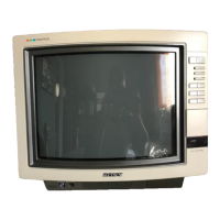
| Screen Size | 13 inches |
|---|---|
| Display Type | CRT |
| Aspect Ratio | 4:3 |
| Weight | 8.6 kg |
| Tuner | NTSC |
| Power Consumption | 65W |
| Inputs/Outputs | Composite Video Input x 1, Coaxial RF Input x 1, Headphone Jack x 1 |
| Inputs | 1 x Composite Video, 1 x RF |
| Speakers | Built-in |
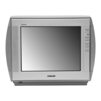
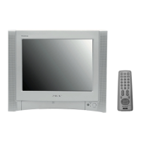
Details technical characteristics like power, dimensions, screen size, and inputs/outputs.
Covers high voltage, critical components, and electrical shock hazards.
Outlines tests for AC leakage and finding a proper earth ground connection.
Explains LED flash codes, screen display interpretation, and how to use the diagnostic function.
Covers rear cover, chassis, service position, picture tube, and anode cap removal.
Details beam landing, convergence, focus, G2 screen, service mode, and white balance procedures.
Procedures for confirming and adjusting HV hold-down and B+ voltage.
Covers service mode setup, memory confirmation, MB board adjustments, and other circuit settings.
Includes circuit board locations, block/schematic diagrams, waveforms, locator lists, and semiconductor visuals.
An exploded view of the chassis with a parts list for identification.
Detailed lists of capacitors, connectors, diodes, fuses, ICs, coils, transistors, resistors, and other parts.