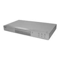
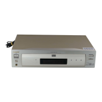
EasyManua.ls Logo

Sony RMT-D175A User Manual

Sony RMT-D175A
90 pages
To Next Page IconTo Next Page
Page #1 background imageLoading...
Page #1 background image
CD/DVD PLAYER
SPECIFICATIONS
SERVICE MANUAL
Photo : DVP-NS78H
DVP-NS72HP/NS77H//NS77HP/NS78H/NS78HP
RMT-D175A/RMT-D175P
AEP Model
DVP-NS78H
Brazilian Model
DVP-NS78H/NS78HP
Canadian Model
DVP-NS78H
E Model
DVP-NS78HP
Korea Model
DVP-NS78H
Mexican Model
DVP-NS77HP
Russian Model
Singapore Model
Thailand Model
UK Model
DVP-NS78H
US Model
DVP-NS72HP/NS77H
System
Laser: Semiconductor laser
Signal format system:
NTSC: (DVP-NS72HP/NS77H:US/
NS77HP:MX/NS78H:CND/
NS78HP:E,BR)
PAL/NTSC: (DVP-NS78H:
AEP,KR,RUS,SP,UK,TH)
Audio characteristics
Frequency response: DVD VIDEO (PCM
48 kHz): 2 Hz to 22 kHz (±0.5 dB)/
CD: 2 Hz to 20 kHz (±0.5 dB)
Wow and flutter: Less than detected value
(±0.001% W PEAK)
Outputs
(Jack name: Jack type/Output level/
Load impedance)
LINE OUT (AUDIO): Phono jack/
2 Vrms/ 10 kilohms
DIGITAL OUT (OPTICAL)
EXCEPT
(DVP-NS78H:AEP,RUS,UK)
Optical output jack/–18 dBm
(wave length 660 nm)
DIGITAL OUT (COAXIAL): Phono jack/
0.5 Vp-p/75 ohms
HDMI OUT: HDMI 19 pin-Standard
Connector
COMPONENT VIDEO OUT
(Y, PB, PR) (DVP-NS72HP/
NS77H:US/NS77HP:MX/
NS78H:CND/NS78HP:E,BR):
Phono jack/Y: 1.0 Vp-p/PB, PR:
interlace
*1
= 0.648 Vp-p, progressive or
interlace
*2
= 0.7 Vp-p/75 ohms
*1
BLACK LEVEL
(COMPONENT OUT) is ON
*2
BLACK LEVEL
(COMPONENT OUT) is OFF
COMPONENT VIDEO OUT
(Y, PB/CB, PR/CR)
(DVP-NS78H:AEP,UK,KR,RUS,SP,TH):
Phono jack/Y: 1.0 Vp-p,
PB/CB, PR/CR: 0.7 Vp-p/75 ohms
LINE OUT (VIDEO): Phono jack/
1.0 Vp-p/75 ohms
S VIDEO OUT
(DVP-NS77H:US/NS77HP:MX/
NS78H:CND/NS78HP:E,BR/
NS72HP:US):
4-pin mini DIN/Y: 1.0 Vp-p,
C: 0.286 Vp-p/75 ohms
S VIDEO OUT
(DVP-NS78H:KR,SP,TH):
4-pin mini DIN/Y: 1.0 Vp-p,
C: 0.3 Vp-p (PAL),
0.286 Vp-p (NTSC)/75 ohms
General
Power requirements:
120 V AC, 60 Hz
(DVP-NS72HP/NS77H:US/
NS77HP:MX/NS78H:CND)
220 – 240 V AC, 50/60 Hz
(DVP-NS78H:AEP,RUS,UK)
110 – 240 V AC, 50/60 Hz
(DVP-NS78H:KR,SP,TH/NS78HP:E/BR)
Power consumption: 11W
Dimensions (approx.):
430 × 43 × 210.4 mm
(17 × 1
11
/16 × 8
2
/7 in.)
(width/height/depth) incl. projecting parts
Mass (approx.): 1.76 kg (3
7
/8 Ib.)
Operating temperature: 5°C to 35°C
Operating humidity: 25% to 80%
Supplied accessories
Audio/video cord (1)
Remote Commander (remote) (1)
R6 (size AA) batteries (2)
HDMI Cord (1) (DVP-NS72HP:US/
NS77HP:MX/NS78HP:E,BR)
A plug adaptor is included in some models
(DVP-NS78HP:E)
Specifications and design are subject to
change without notice.

Table of Contents

Questions and Answers:

Sony RMT-D175A Specifications

General IconGeneral
TypeRemote Control
BrandSony
ModelRMT-D175A
Compatible DevicesDVD Player
Remote Control TechnologyInfrared
Battery TypeAA
Number of Batteries2

Summary

Safety Check-Out Procedures

General Safety Checks

Pre-release checks for safety and proper repair.

AC Leakage Test

Procedure for measuring AC leakage current from exposed metal parts.

Service Notes

Initial Setup and Basic Playback

Quick Setup Guide

Guided initial setup for language, display, and audio.

System Settings and Display Configuration

Customization and Audio Settings

Troubleshooting and Self-Diagnosis

Self-Diagnosis Functionality

How to use the built-in diagnostic function for troubleshooting.

Disassembly Procedures

Block Diagrams - System Overview

Wiring Boards and Schematic Diagrams

Waveforms and Board Documentation

IC Pin Function Descriptions

System Control IC (IC101) Pinout

Pinout details for the system control IC (IC101) on MV-55/56 boards.

Test Mode Procedures

Executing IOP Measurement

Steps for performing IOP measurement using the test mode.

Emergency History Check

How to check the unit's emergency history log.

Setup Initialization and Version Information

Initializing Setup Data

Procedure for resetting all setup data to default values.

Clearing Emergency History

How to clear emergency history logs and laser hours.

Self-Diagnostic Functions

IF-154 Board Test Mode Functionality

Describes the IF-154 board's independent test mode functions.

Self Check Mode Operation

How to enter and perform self-check tests on the FLD and DVD panel.

Auto Self Check and Key Input Tests

Self Check Functionality Tests

Testing FLD display, LED display, and key inputs in self-check mode.

Remote Commander and Communication Diagnostics

Remote Key Display and Communication Monitoring

Displaying remote key names and monitoring communication status.

FLD Anode Test and Shuttle Click Test

Testing FLD segments and shuttle click operation.

Display Grid and LED Diagnostics

FLD Grid Test and Shuttle Direction

Testing FLD grid segments and shuttle direction input.

LED Test Display Functionality

Testing LED indicators using remote commands.

Electrical Adjustment Procedures

Power Supply Voltage Output Check

Verifying output voltages of the power supply unit.

Video System Adjustment and Checks

Video Level and Scart Output Checks

Checking video levels for LINE OUT and Scart S-Video output.

Scart S-Video Output S-C Check

Checking the S-Video S-C signal level for correct color display.

RGB and Component Video Adjustments

RGB Output Level Checks (G, B, R)

Checking the output levels for Red, Green, and Blue video signals.

Component Video Y Output Check

Verifying the Y component video output level.

Component Video Output Adjustments (Continued)

Component Video B-Y and R-Y Output Checks

Checking the B-Y and R-Y component video output levels.

Repair Parts Information

Exploded Views - Main Section Assembly

Visual exploded view of the main player assembly with parts.

Main Section Parts List (Specific Models)

Part numbers for main section components for various models.

Exploded Views - Specific Models (AEP, UK, RUS)

Visual exploded view for AEP, UK, and RUS models.

Parts List - Specific Models (AEP, UK, RUS)

Part numbers for components in AEP, UK, and RUS models.

Exploded View - Mechanism Deck Assembly

Visual exploded view of the disc loading and mechanism deck assembly.

Electrical Parts List - IF-154 Board

IF-154 Board Component Details

List of components for the IF-154 interface board.

Electrical Parts List - MV-55 Board

IF-154 and MV-55 Board Components

List of components for IF-154 and MV-55 boards.

MV-55 Board Component Details

List of components for the MV-55 board.

MV-55 Board Components (Continued)

Continuation of component list for the MV-55 board.

Electrical Parts List - MV-56 Board

MV-56 Board Component Details

List of components for the MV-56 board.

MV-55 and MV-56 Board Components

List of components for both MV-55 and MV-56 boards.

MV-56 Board Components (Continued)

Further continuation of component list for the MV-56 board.