5-10
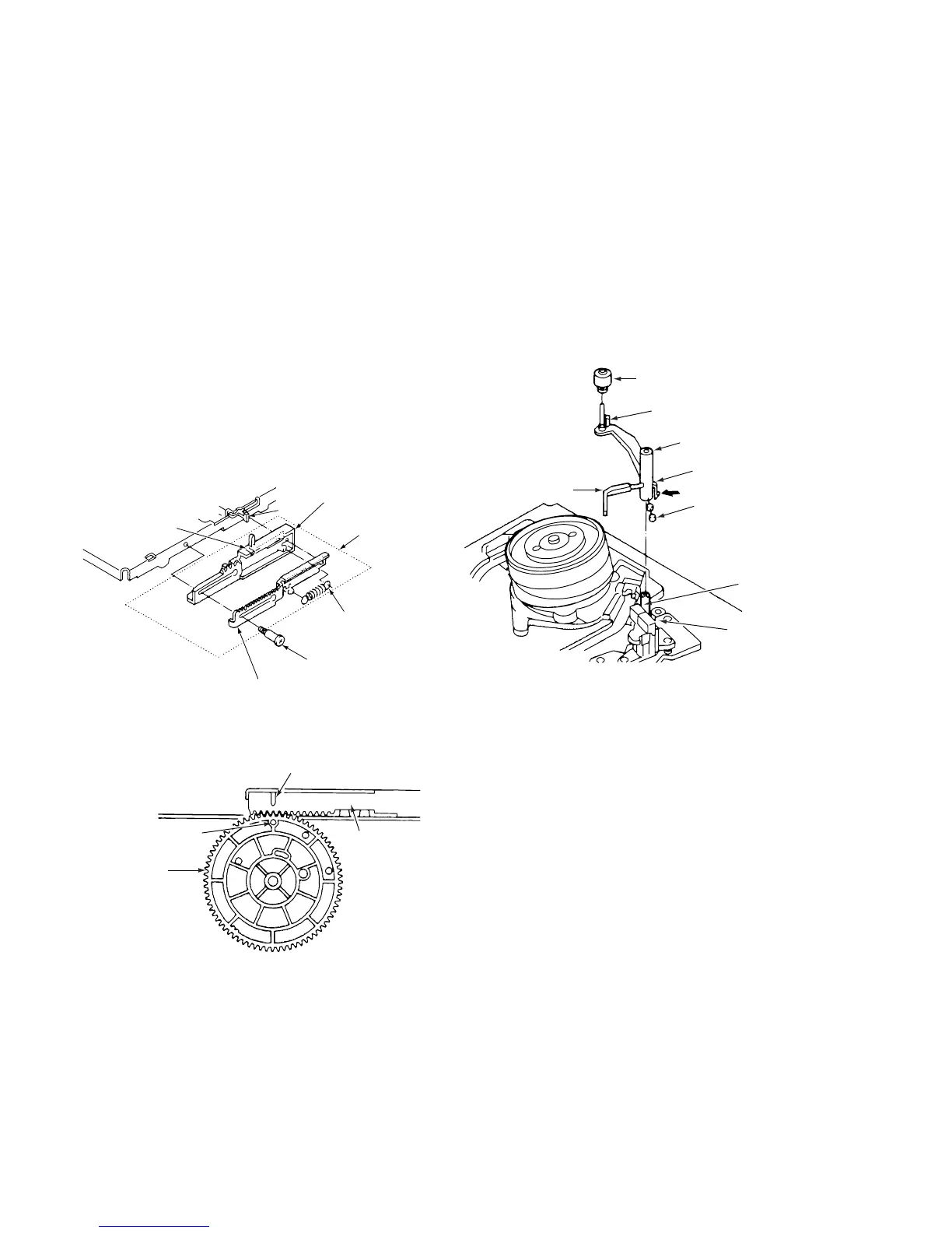
3-3-4. START RACK GEAR AND FRONT RACK
GEAR (See Figs. 3-3-5 and 3-3-6)
1) Remove the mechanism unit, referring to section 3-2.
2) Remove the cassette mechanism assembly, referring to
section 3-3-1.
3) Remove the special screw 1. When you dothis, slide
the front rack gear assembly 2 towards the front until it
stops, then take it off the shaft 3. Take care not to
damage the shaft 3.
4) Remove the spring 4.
5) Remove the clamp 6 on the front rack gear 5, then
remove the start rack gear 7.
ASSEMBLY NOTES:
1. Apply grease (VHJ-0100) to the front rack gear 5 and
all over the inside of the groove on the start rack gear
7.
2. Align the positioning mark 8 on the front rack gear 5
with the mark 0 on the main cam 9.
3. When installing the cassette mechanism assembly,
refer to section 3-3-1 and align the start rack gear with
the pinion gear.
6 Clamp
1 Special screw
4 Spring
7 Start rack gear
(apply grease to
inside of groove)
5 Front rack gear
(apply grease to
inside of groove)
3
Shaft
2 Front rack
gear assembly
Fig.3-3-5
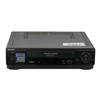
8 Positioning mark
5 Front rack
gear
0 Positioning mark
9 Main cam
Flg.3-3-6
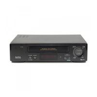
3-4. CLEANER ROLLER ASSEMBLY
(See Fig. 3-4-1 )
1) Remove the clamp 1 and take out the cleaner lever 2.
When you do this, be careful not to bend the plastic
springs A and B on the cleaner lever 2.
2) Remove the clamp 3, and take out the cleaner roller
assembly 4. Be careful not to touch the sponge on the
cleaner roller assembly 4.
ASSEMBLY NOTES:
1. When mounting the cleaner lever 2 on the shaft 5,
press the clamp 1 in the direction shown by the arrow,
and snap it into the mounting 6 on the audio R/P head
assembly.
4 Cleaner roller assembly
3 Clamp
2 Cleaner lever
1 Clamp
A Plastic spring
5 Shaft
6 Mounting
B Plastic spring
Fig.3-4-1