5-22
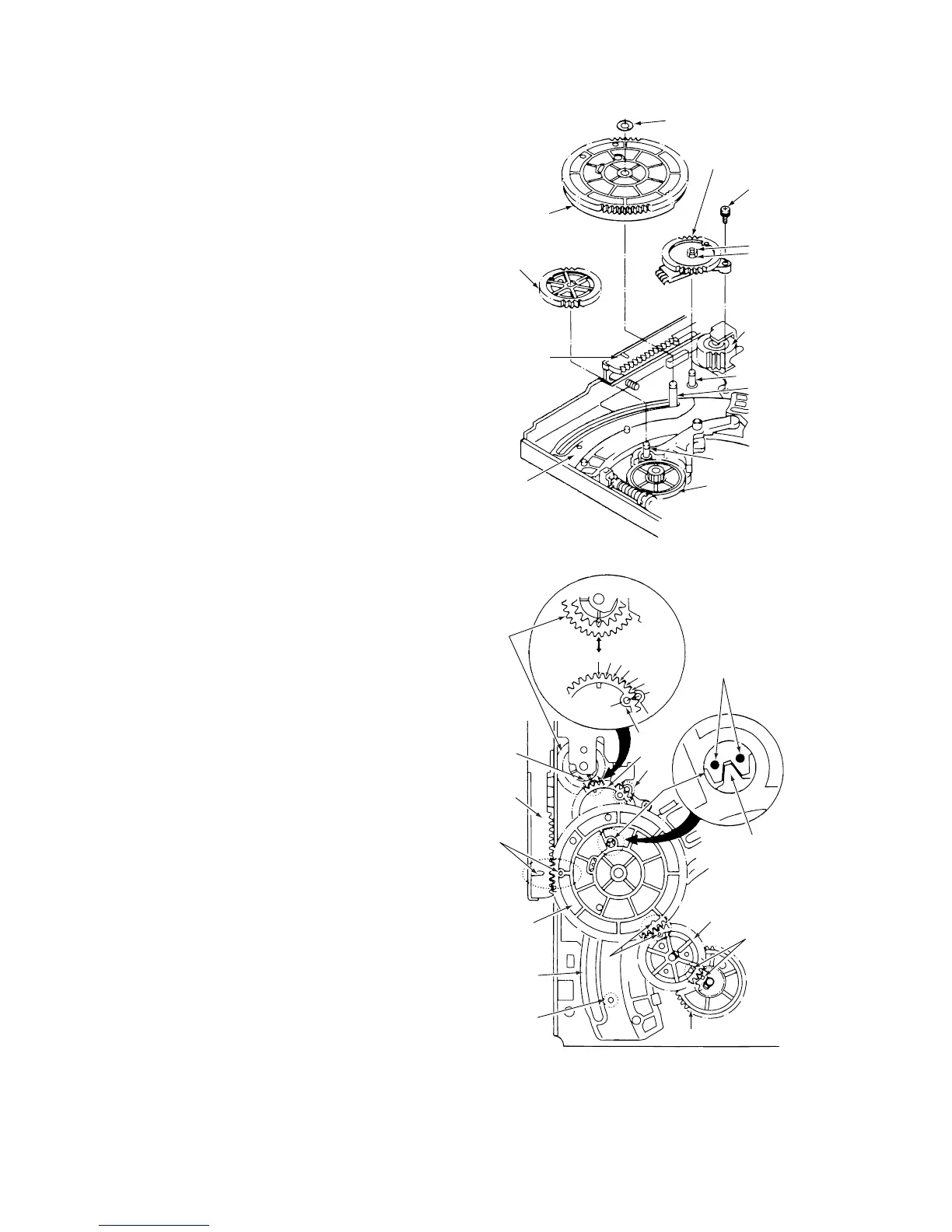
3-15. WHEEL GEAR 2, MAIN CAM AND
MODE SWITCH
(See Figs. 3-15-1 and 3-15-2)
1) Refer to section 3-2 and remove the mechanism unit.
When you do this, make sure the mechanism is in
EJECT mode.
2) Refer to section 3-7-1, then remove the harness
mounting.
3) Remove the clamp 1, then remove the wheel gear 2 2.
4) Remove the washer 3, then remove the main cam 4.
5) After unscrewing the screw 5, remove the soldering
from the terminal of the mode switch 6.
6) Remove the clamp 7, then remove the mode switch 6.
ASSEMBLY NOTES:
1. Apply grease (VHJ-0100) to the shafts 8, 9 and 0, to
the teeth of the main cam 4, and to the all over the
cam groove of main cam 4.
2. When fitting the modes witch 6, align it in AB order
as shown in Fig. 3-15-2. The alignment of the part B is
shown in Fig. A. Position the teeth of the mode switch
6 so that the sixth tooth space left of part A is aligned
with the triangular mark on the pinch cam gear !¡. After
aligning part B, refer to section 3-9-2 and check the
positioning of the mode switch, the pinch cam gear and
the pinch lift cam.
3. Beforehand, remove the soldering from the soldered
part of the MC-1 PWB assembly, in order to prevent the
mode switch 6 being warped. Solder the mode switch
6 after tightening the screw 5 (See Fig. 3-15-1 ) .
4. Align the hole in the crescent slide !™ with the hole in
the mechanism chassis, as shown at point G in Fig. 3-
15-2 (refer to section 3-16 and see the holes 5 and 6
in Fig. 3-16-1).
5. When fitting the main cam 4, position the mode switch
6 and the front rack gear !£ as shown at points C and
D respectively in Fig. 3-15-2.
6. When fitting the gear wheel 2 2, position the main cam
4 and the wheel gear 1 !¢ as shown at points E and
F respectively in Fig. 3-15-2.
3 Washer
6 Mode switch
7 Clamp
5 Screw
4 Main cam
2 Wheel
gear 2
!¢ Wheel
gear 1
!£ Front rack
gear
9 Shaft
8 Shaft
0 Shaft
!™ Crescent slide
!¡ Pinch
cam
gear
Fig. 3-15-1
2 Wheel gear 2
!¢ Wheel gear 1
4 Main cam
!™ Crescent
slide
!¡ Pinch
cam
gear
!£ Front
rack
gear
6
Mode
Fig. A
6
5
4
3
2
1
Align at B
Marks on mode
switch 6
A
B
F
G
E
D
C
Tooth tip on
main cam 4
switch
Fig. 3-15-2