5-16
3-9-2. PINCH LIFT CAM AND PINCH CAM GEAR
(See Figs. 3-9-2 and 3-9-3)
1) Refer to section 3-2 and remove the mechanism unit.
When you do this, make sure the mechanism is in
EJECT mode.
2) Refer to section 3-9-1 and remove the pinch roller lever
assembly.
3) After removing the screw 1, undo the three clamps 2,
then remove the opener mounting 3.
4) Remove the clamp 4 and the pinch lift cam 5.
5) Remove the pinch cam gear 6.
ASSEMBLY NOTES:
1. Apply grease (VHJ-0100) around the shaft 7, all over
the teeth B of the pinch cam gear 6, all over the teeth
of the pinch lift cam 5, all over the cam grooves A,
and all over the “V Part C” of the opener mounting 3.
Apply grease (VHJ-0101) to the outside of the shaft 8
and all over the top cam D of the pinch cam gear 6.
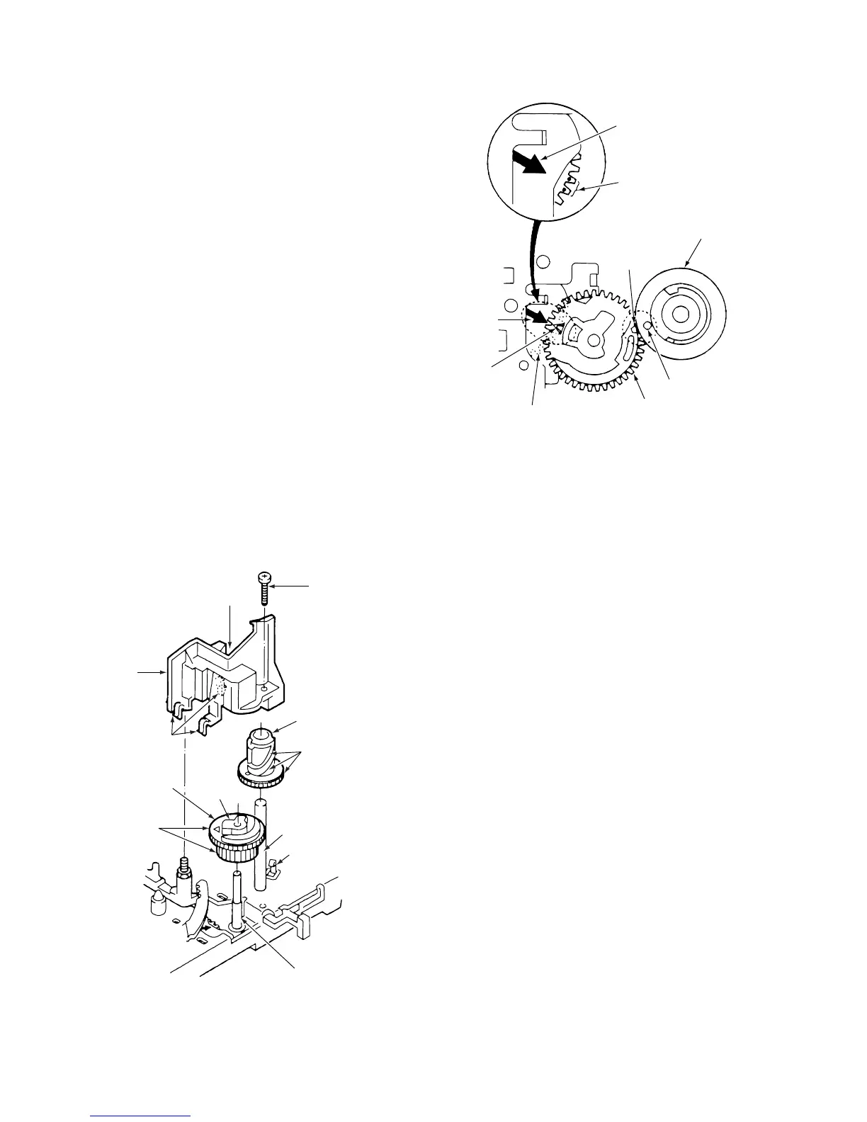
2. Check that the positioning mark 0 on the mode switch
9 is aligned with the arrow !¡ on the MC-1 PWB
assembly, as shown in Fig. 3-9-3. Then align the
triangular mark !™ on the pinch cam gear 6 with the
arrow !¡ on the MC-1 PWB assembly. After that, align
the round hole !£ on the pinch lift cam 5 with the
indentation !¢ on the pinch cam gear 6.
If you have carried out the above alignments and the
pinch roller will still not move up and down or perform
the pressing movement correctly, refer to section 3-15
and check the alignment of the gear wheels 1 and 2,
the main cam, and the mode switch.
6 Pinch cam gear
1 Screw
3 Opener
mounting
A
D
B
4 Clamp
8 Shaft
5 Pinch lift cam
2 Clamps
7 Shaft
C “ V “ part
Fig. 3-9-2
!™ Triangular mark
!¢
Indentation
!¡ Arrow
0 Positioning marks
on mode switch
!¡ Arrow on MC-1 PWB
assembly
5 Pinch lift cam
9 Mode switch
6 Pinch cam gear
!£ Round hole
Fig. 3-9-3