6-6
2-2. VIDEO CIRCUIT RELAY JIG
2-2-1 .TEST EQUIPMENT AND STANDARDS REQUIRED
Color Bar Signal Generator PAL Color bar signel with 100% white level (EBU color bar signel)
Oscilloscope Vertical sensitivity : 5 mV/DIV, external trigger
Bandwidth : more than 10 MHz
Oscilloscope Probe Input capacity : less than 25 pF (10:1)
less than 40 pF (1:1)
Covering frequency : DC ~ 40 MHz (10:1)
DC ~30 MHz (1:1)
Digital Voltmeter DC range
Alignment Tape VHJ-0008 or VHJ-0023 : SP mode, color bar. 1 kHz
(Color bar signal waveform is described below. Refer to Fig. 2-2-1)
Relay Jig VHJ-0065 : 5-wire flat cable for VP-1 PWB assembly (2 head model)
VHJ-0066 : 7-wire flat cable for VP-1 PWB assembly (4 head model)
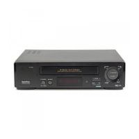
RELAY JIG
Connect the flat cable end from the cylinder assembly to
the VP-1 PWB assembly using the relay jig to provide
simple repairing of the VP-1 PWB assembly, as shown in
Fig. 2-2-3. Further, when adjusting the VP-1 PWB assem-
bly, be sure to make contact an end of shield case with
bracket of the VP-1 PWB assembly to maintain the shield
effect. If the VP-1 PWB assembly does not contact, there
is insufficient ground and no proper play back image can
be obtained.
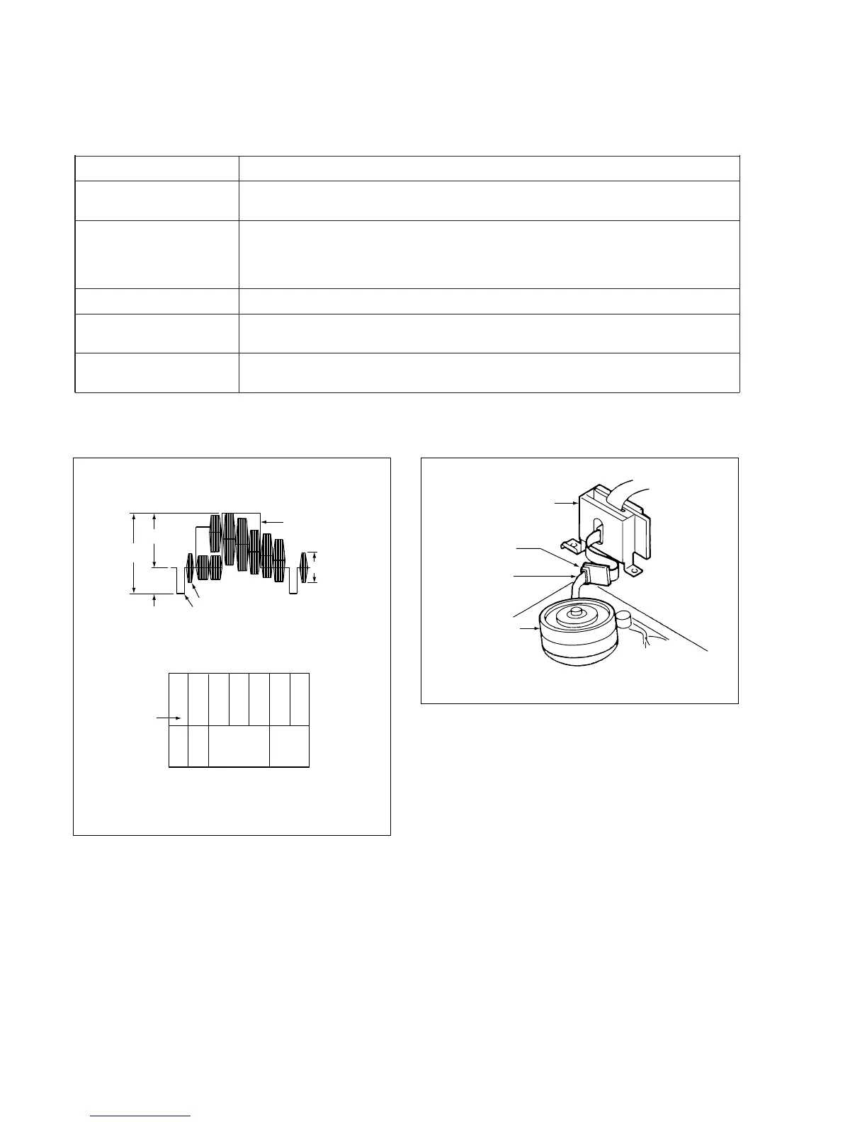
ALIGNMENT TAPE COLOR BAR SIGNAL
Color bar signal waveform (VHJ-0008)
Color bar pattern (VHJ-0008) on monitor TV
Cyan
Green
Magenta
Red
Blue
1Vp-p
0.7Vp-p
0.3Vp-p
V U
Black
0.3Vp-p
100% White
100%
White
Burst signal
H. Sync signal
75%
White
Yellow
Cyan
Green
Magenta
Red
Blue
(75%)
White
Yellow
Fig. 2-2-1
Fig. 2-2-2
Relay Jig
VHJ-0065
or
VHJ-0066
Fig. 2-2-3
VP-1 PWB Assembly
Flat Cable
Cylinder
Assembly