5-21
3-14.GUIDES
3-14-1. GUIDE ROLLER ASSEMBLY
(See Fig. 3-14-1)
1) Unscrew the two screws 1. When you do this, be
careful not to damage the cylinder or the video head.
2) Remove the two guide roller assemblies 2 by unscrew-
ing them anticlockwise.
ASSEMBLY NOTES:
1. Tighten the two screws 1 to a torque of 600 g/cm. After
tightening, apply a screw-locking glue.
2. After replacing the parts, be sure to clean the guide
roller and carry out tape path adjustment as described
in section 4-3.
1 Screw
1 Screw
2 Guide
roller
assembly
2 Guide
roller
assembly
Fig. 3-14-1
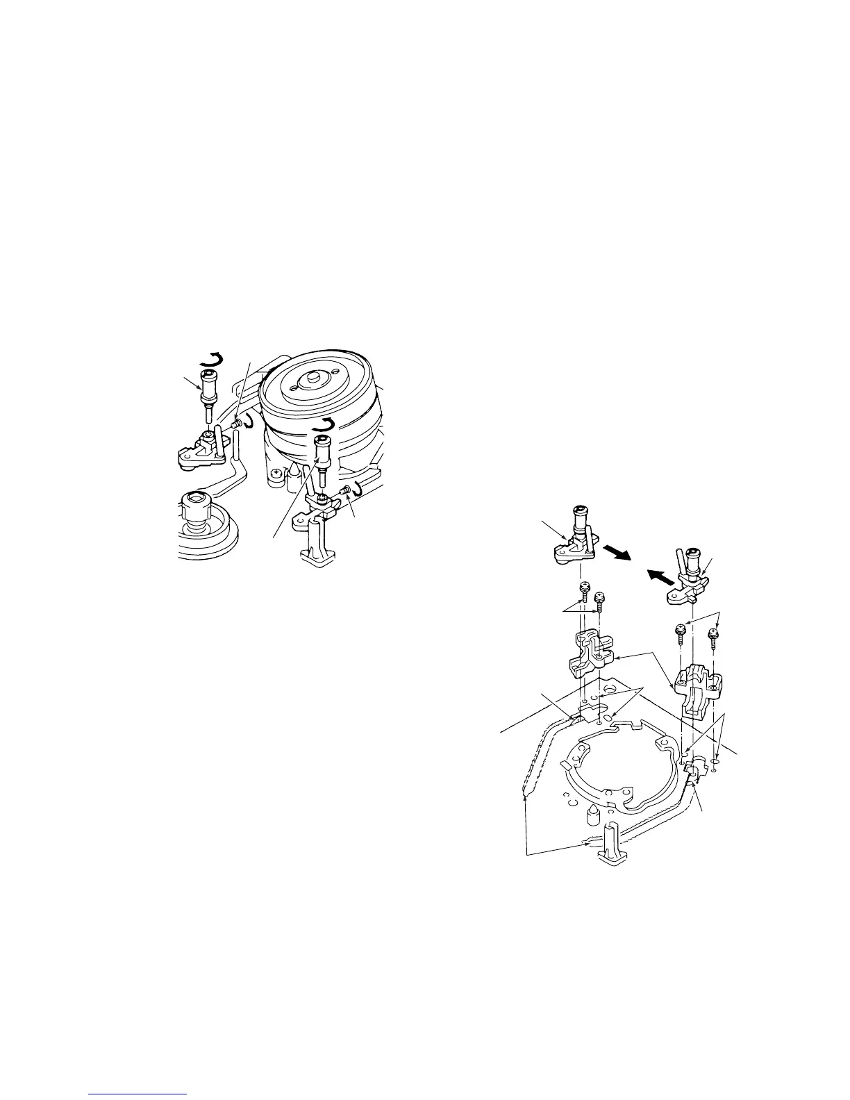
3-14-2. S AND T INCLINE MOUNTING
ASSEMBLIES (See Fig. 3-14-2)
1) Refer to section 3-2 and remove the mechanism unit.
2) Refer to section 3-4 and remove the cleaner lever.
3) Remove the four screws 5 and take off the two catcher
mountings 6.
4) Refer to section 3-1 and rotate the loading motor in the
PLAY direction until tape loading is completed.
5) Shift the S incline mounting assembly 1 slightly, in the
direction of the arrow A, then remove it from the S load
lever assembly 2.
6) Shift the T incline mounting assembly 3 slightly, in the
direction of the arrow B, then remove it from the T load
lever assembly 4.
ASSEMBLY NOTES:
1. Apply grease (VHJ-0100) to the rail (top, underside and
sides) on the mechanism chassis.
2. When fitting the S and T incline mounting assemblies 1
and 3 into the rail, turn the loading motor manually in
the EJECT direction. When tape unloading begins,
watch out in case the S and T incline mounting assem-
blies 1 and 3 get caught in the rail.
3. Aline the dowels on the catcher mounting 6 with the
holes 7 in the mechanism chassis.
4. After repiacing the parts, clean the cylinder and the
roller guide, then adjust the tape path as described in
section 4-3.