6-7
2-3. IF CIRCUIT ADJUSTMENT
• In this model, the circuits of the TUNER, IF, and RF
converter have been made into one. Therefore, should
one circuit malfunction, the whole unit must be replaced.
• The adjustments for the IF (RF AGC) circuit of the 3 in 1
tuner are described below.
Note: The 3 in tuner dose not need any adjustments,
because precise adjustments were down before
shipment.
2-3-1. TEST EQUIPMENT AND STANDARD REQUIRED
Monitor TV
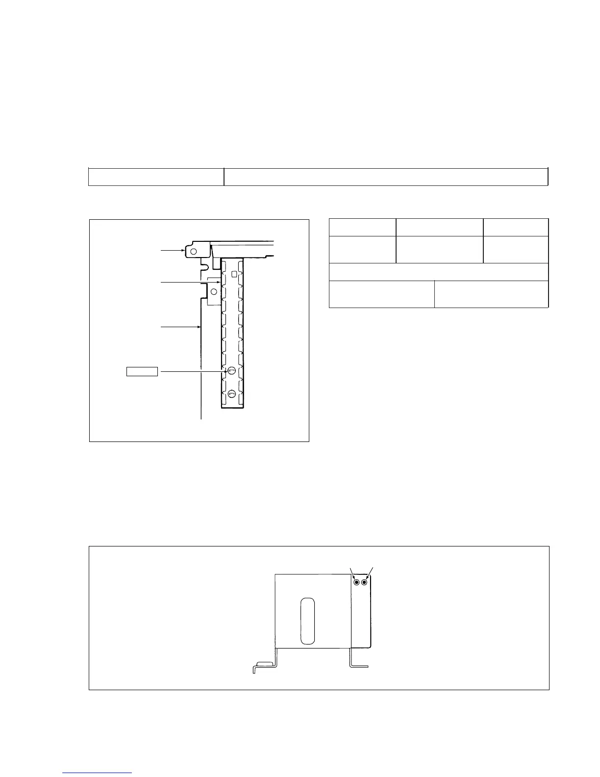
2-3-2. LOCATION OF ADJUSTMENT POINT
3 in 1 Tuner
Rear Panel
3 in 1 Tuner
CP-1 PWB
Assembly
Fig. 2-3-1
VR RF AGC
2-3-3. RF AGC ADJ.
1. Connect the monitor TV to the VHF/UHF antenna
output terminal.
2. Connect the VHF or UHF antenna to the VHF/UHF
antenna input terminal.
3. Receive the middle electrical field (70 dBµ ~90 dBµ) of
the VHF or UHF channel, and slowly turn the VR (RF
AGC) from the point where snow-noise is present to the
point where it just disappears from the monitor TV.
4. Confirm by monitor TV that there is no beat and
saturation (S/N is best point) when receiving any TV
channel.
Measuring Point Measuring Equipment Adj. Condition
Picture of Monitor TV E-E mode
monitor TV
Adj. Location Adj. Value
VR (RF AGC) S/N is best point
(on the 3 in 1 tuner)
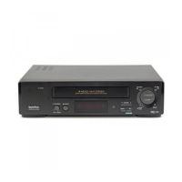
3. TEST POINTS FOR TAPE PATH ADJUSTMENT
Test points TP182 (ENV) and TP183 (SW-P) for tape path adjustment are shown in figure below.
VP-1 PWB Assembly
TP182
(ENV.)
TP183
(SW-P)
Fig. 3-1
E