5-20
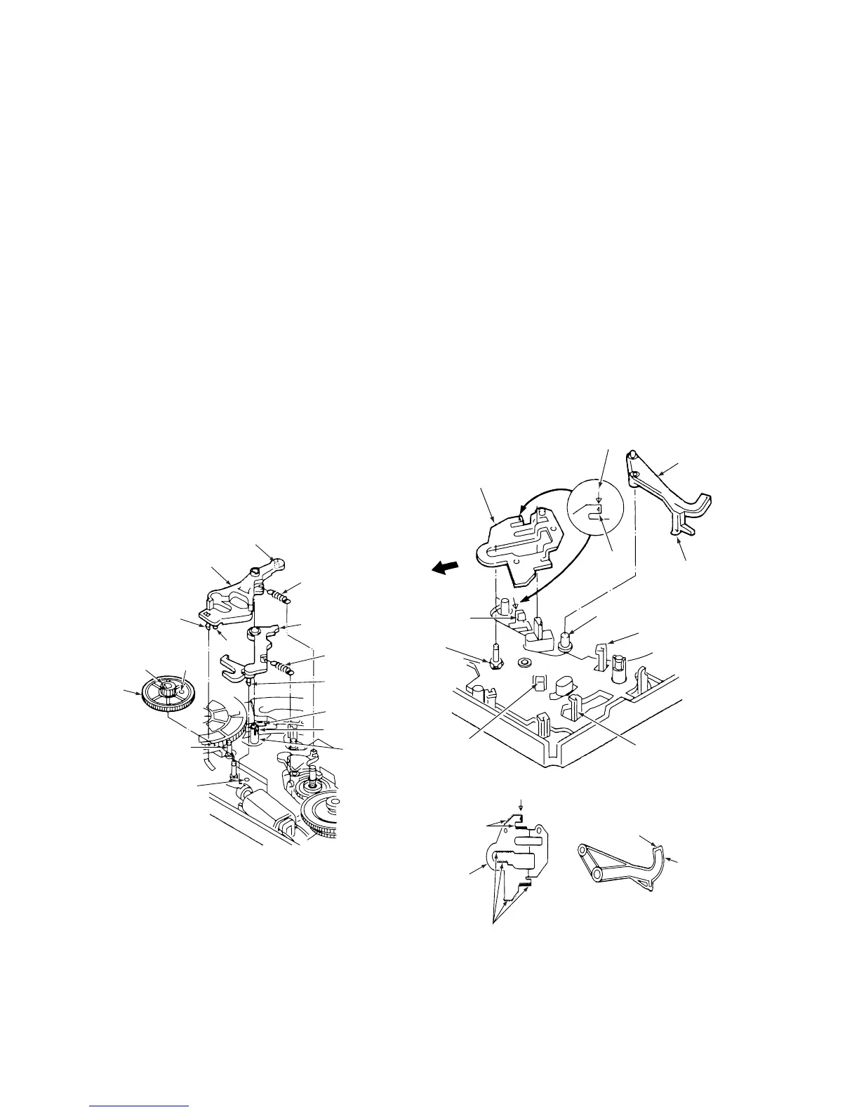
3-13-2. BRAKE CONTROL LEVER AND BRAKE
ACT LEVER ASSEMBLY (See Fig. 3-13-2)
1) Refer to section 3-2 and remove the mechanism unit.
2) Refer to section 3-15 and remove the wheel gear 2.
3) Refer to sections 3-12-1, then remove the reel belt and
the reel pulley.
4) Remove the clamp 1, then remove the wheel gear 1
2.
5) Remove the clutch change spring 3.
6) Remove the clamps 4 and 5, then remove the brake
control lever 6. Remove the clamp 4 on the topside of
the mechanlsm chassis.
7) Remove the brake return spring 7.
8) Refer to section 3-8 and remove the worm gear assem-
bly.
9) Remove the clamp 8 and clamp 5, then remove the
brake act lever assembly 9. To maintain the perfor-
mance of the brake act lever assembly 9, do not
disassemble it.
ASSEMBLY NOTES:
1. Apply grease (VHJ-0100) to the shafts 0 and !¡, to the
teeth of the wheel gear 1 2. and to the pin !™ of the
brake control lever 6 .
2. Put the pin !£ of the brake control lever 6 into the cam
groove !¢ of the crescent slide.
3. Before fitting the wheel gear 1 2 , align the hole !∞ with
the hole !§ on the mechanism chassis.
4. Refer to section 3-15 and align the wheel gear 2.
!£ Pin
!™ Pin
6 Brake control lever
8 Clamp
5 Clamp
0 Shaft
!¡ Shaft
!§ Hole
4 Clamp
!∞ Hole
1 Clamp
2 Wheel
gear 1
3 Clutch change
spring
9 Brake act
lever assembly
7 Brake return
spring
!¢ Cam
groove
Fig. 3-13-2
3-13-3. S BRAKE ACT SLIDE AND BT SPRING
LEVER ASSEMBLY
(See Figs. 3-13-3 and 3-13-4)
1) Refer to section 3-16 and remove the crescent slide.
2) Refer to section 3-12-1 and remove the friction gear
assembly.
3) Slide the S brake act slide 1 in the direction of the
arrow A , then remove it.
4) Refer to section 3-11 and remove the BTspring.
5) Press the BTspring lever assembly 2 until it touches
the pin 3, then remove it.
ASSEMBLY NOTES:
1. Apply grease (VHJ-0100) to the shaft 4 shown in Fig.
3-13-3, and to the BT spring lever assembiy 2 and the
S brake act slide 1 shown in Fig. 3-13-4.
2. After mounting the BT spring lever assembly 2 on the
Shaft 4, hook the BT spring onto the clamp 5 and
press it until it touches the pin 6.
3. Make sure that the clamps 7, 8 and 9 have snapped
Into the S brake act slide 1. Align the arrow 0 on the
S brake act slide 1 with the arrow !¡ on the mecha-
nism chassis.
5 Clamp
!¡ Arrow on mechanism chassis
1 S brake act slide
7 Clamp
9 Clamp
8 Clamp
3 Pin
6 Pin
A
4 Shaft
0 Arrow
2 BT spring
lever
assembly
Fig. 3-13-3
Apply grease
Apply grease
Apply grease
2 BT spring
lever
assembly
1 S brake
act
slide
Fig. 3-13-4