5-17
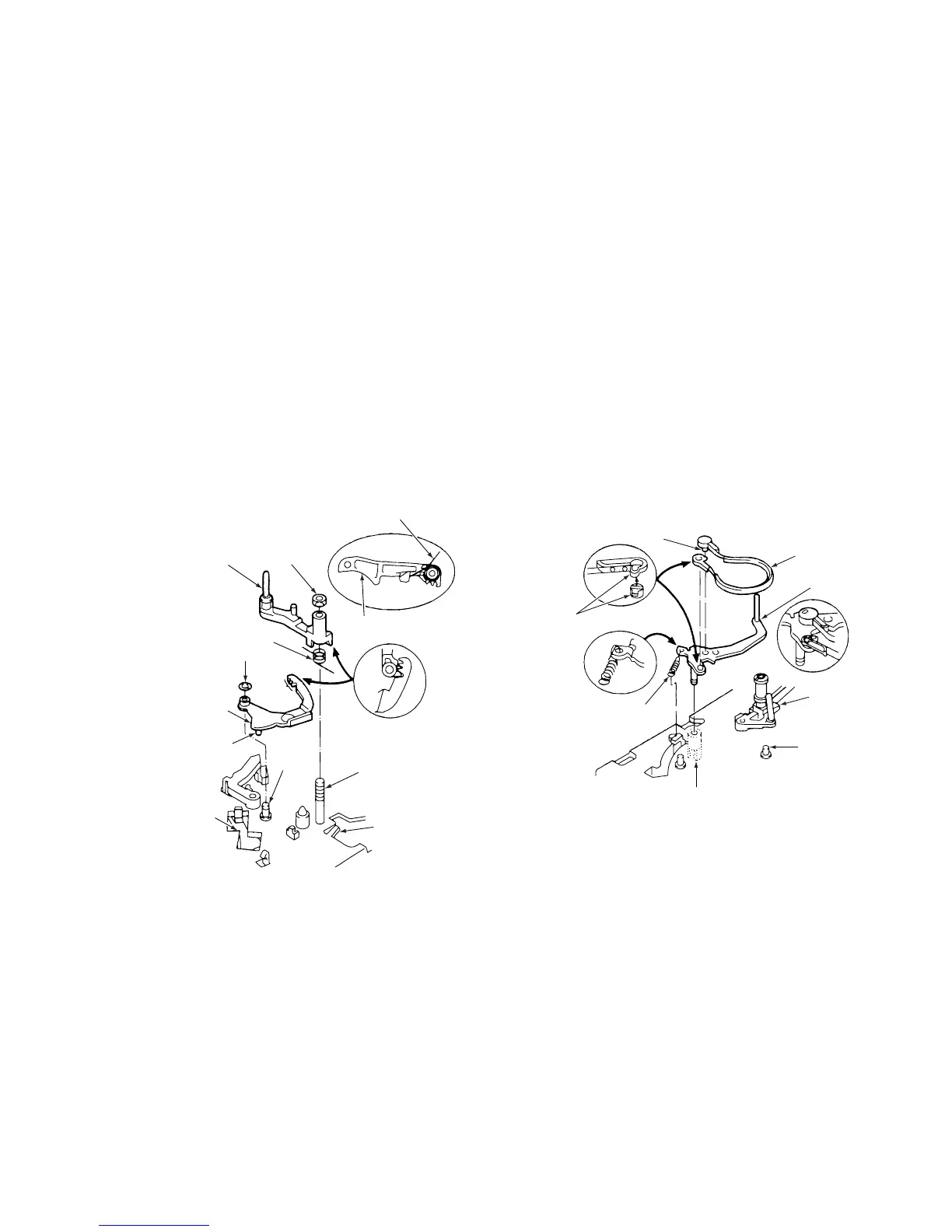
3-10.L GUIDE LEVER ASSEMBLY AND
LOAD LEVER ASSEMBLY
(See Figs. 3-10-1 )
1) Refer to section 3-3 and remove the cassette mecha-
nism assembly.
2) Refer to sections 3-9-1 and 3-9-2, then remove the
pinch roller lever assembly and the opener mounting.
3) After removing the washer 4, remove the L guide act
lever assembly 5.
4) Remove the special nut 6, then remove the load lever
assembly 7 and the L guide lever spring 8.
ASSEMBLY NOTES:
1) Apply grease (VHJ-0100) to the toothed area A of the
L guide act lever assembly 5 and around the shafts 9
and 0.
2) Refer to section 4-3 and adjust the height of the load
lever assembly.
3) Hook the L guide lever spring 8 into the stopper !£
and load lever assembly 7 shown in Fig. A.
4) Put the pin !¡ of the L guide act lever assembly into the
cam groove !™ of the crescent slide.
7 Load lever assembly
8 L guide lever spring
4 Washer
5 L guide
act lever
assembly
8 L guide lever spring
6 Special nut
7 Load lever
assembly
!¡ Pin
0 Shaft
9 Shaft
A
!£ Stopper
!™ Cam groove
Fig. A
Fig.3-10-1
3-11.BT LEVER ASSEMBLY
(See Fig. 3-11-1 )
1) Refer to section 3-2 and remove the mechanism unit.
2) Refer to section 3-3-1 and remove the cassette mecha-
nism assembly.
3) Remove the BT spring 1.
4) Remove the clamp 2 on the underside of the mecha-
nism chassis, then remove the BT lever assembly 3.
5) Remove the clamp 5 on the band brake assembly 4.
Then, as shown in Fig. A, align the other end of the
band brake assembly with the protruding parts of the
BT lever assembly 3 before removing it.
ASSEMBLY NOTES:
1. When fitting the BT lever assembly 3, be careful not to
bend the stopper 6 or the S incline mounting assembly
7 out of shape by knocking it against them.
2. Hook the long hook of the BT spring 1 into the BT
Iever assembly 3, as shown in Fig. B.
3. After assembly. make sure that the mountings on both
ends of the band brake assembly 4 are positioned as
shown in Fig. C.
4. After assembly, refer to section 4-2-1, and make the
appropriate adjustment.
Protruding
parts
2 Clamp
5 Clamp
6 Stopper
7 S incline
mounting
assembly
1 BT spring
4 Band brake
assembly
3 BT lever
assembly
Fig. A
Fig. B
Fig. C
Fig. 3-11-1