5-18
3-12.REEL DRIVE MECHANISM
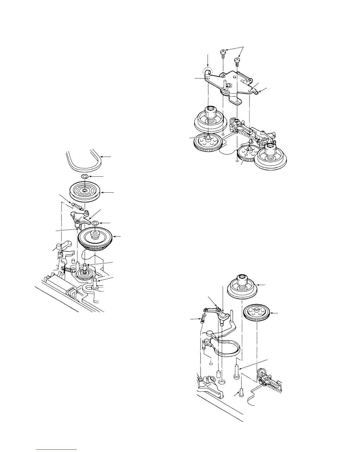
3-12-1. REEL BELT, REEL PULLEY, FRICTION
GEAR ASSEMBLY AND CLUTCH CHANGE
LEVER (See Fig. 3-12-1)
1) Refer to section 3-2 and remove the mechanism unit.
2) Remove the reel belt 1 from the reel pulley 2.
3) Take off the washer 3 and remove the reel pulley 2.
4) Take off the washer 4 and remove the friction gear
assembly 5.
5) Remove the clutch change spring 6.
6) Remove the clamp 7 gripping the top of the mecha-
nism chassis, then remove the clutch change lever 8.
ASSEMBLY NOTES:
1. After cleaning the shafts 9 and 0, apply a drop of oil
(VHJ-0099) to each.
2. Be careful not to get any grease on the reel belt 1.
1 Reel belt
3 Washer
2 Reel pulley
8 Clutch change lever
4 Washer
5 Friction gear
assembly
9 Shaft
0 Shaft
7 Clamp
6 Clutch change
spring
Fig. 3-12-1
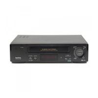
3-12-2. CLUTCH MOUNTING ASSEMBLY
(See Fig.3-12-2)
1) Refer to section 3-3-1 and remove the cassette mecha-
nism assembly.
2) Refer to section 3-12-1 and remove the reel pulley.
3) Remove the two screws 1, then remove the clutch
mounting assembly 2.
ASSEMBLY NOTES:
1. Align the two holes 3 with the shafts 4 and 5. Be
careful not to press part A of the clutch mounting
assembly 2 against the band brake assembly.
2. After assembly, make sure that the clamp on the clutch
change lever has snapped into the chassis.
1 Screws
3 Hole
2 Clutch
mounting
assembly
5 Shaft
4 Shaft
3 Hole
Part A
Fig. 3-12-2
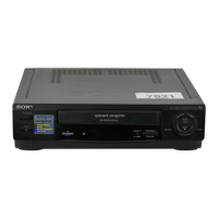
3-12-3. S SOFT LEVER, SUPPLY REEL ASSEM-
BLY AND S REEL GEAR (See Fig. 3-12-3)
1) Remove the S soft spring 1.
2) Remove the clamp 2, then remove the S soft lever 3.
3) Refer to section 3-12-2 and remove the clutch mounting
assembly.
4) Refer to section 3-11 and remove the band brake
assembly, then remove the supply reel assembly 4 and
the S reel gear 5.
ASSEMBLY NOTES:
1. After cleaning the shafts 6 and 7, apply a drop of oil
(VHJ-0099) to each.
2. After assembly, clean the side of the supply reel assem-
bly 4.
7 Shaft
6 Shaft
5 S reel
gear
4 Supply reel
assembly
3 S soft lever
2 Clamp
1 S soft
spring
Fig. 3-12-3