12
STR-DB798
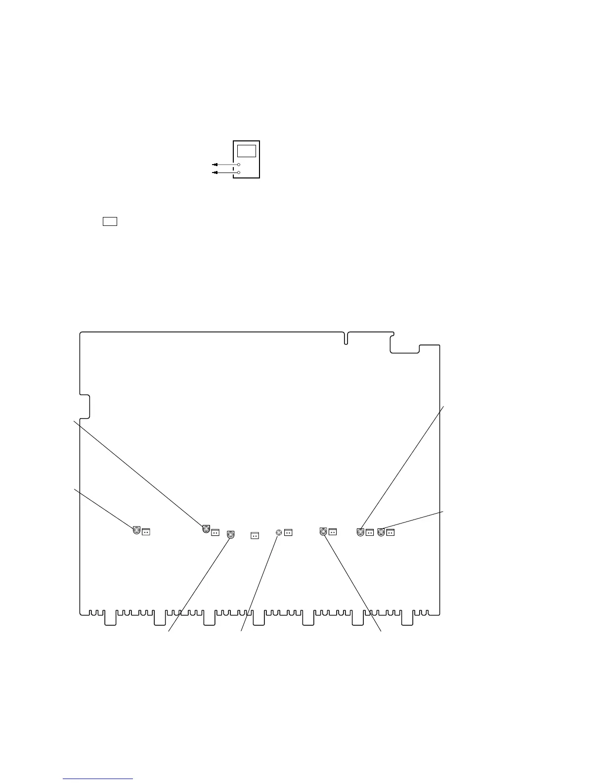
BIAS ADJUSTMENT
Condition:
input signal: no signal (no load)
volume: minimum
Connection
Procedure:
1. Connect a digital voltmeter to the CN432 (CN482, CN532,
CN582, CN632, CN682, CN732) on the MAIN board.
2. Press the I/1 button to turn on the main power.
3. Adjust the RV431 (RV481, RV531, RV581, RV631, RV681,
RV731) on the MAIN board so that the digital voltmeter
reading is 15±2 mV.
Note: When the adjusting voltage is higher than 15±2 mV, adjust the
voltage to the minimum voltage.
Adjustment and Connection Loacation:
+
–
digital voltmeter
CN432 (CN482, 532, 582, 632, 682, 732) pin
1
CN432 (CN482, 532, 582, 632, 682, 732) pin
2
CN432
CN482
CN532
CN582
CN632
CN682
RV581
RV531
RV631 RV681
RV481
RV731
CN732
21
21
21
21
21
12
21
RV431
– MAIN Board (Component Side) –
SECTION 5
ELECTRICAL ADJUSTMENTS