69
STR-DB798
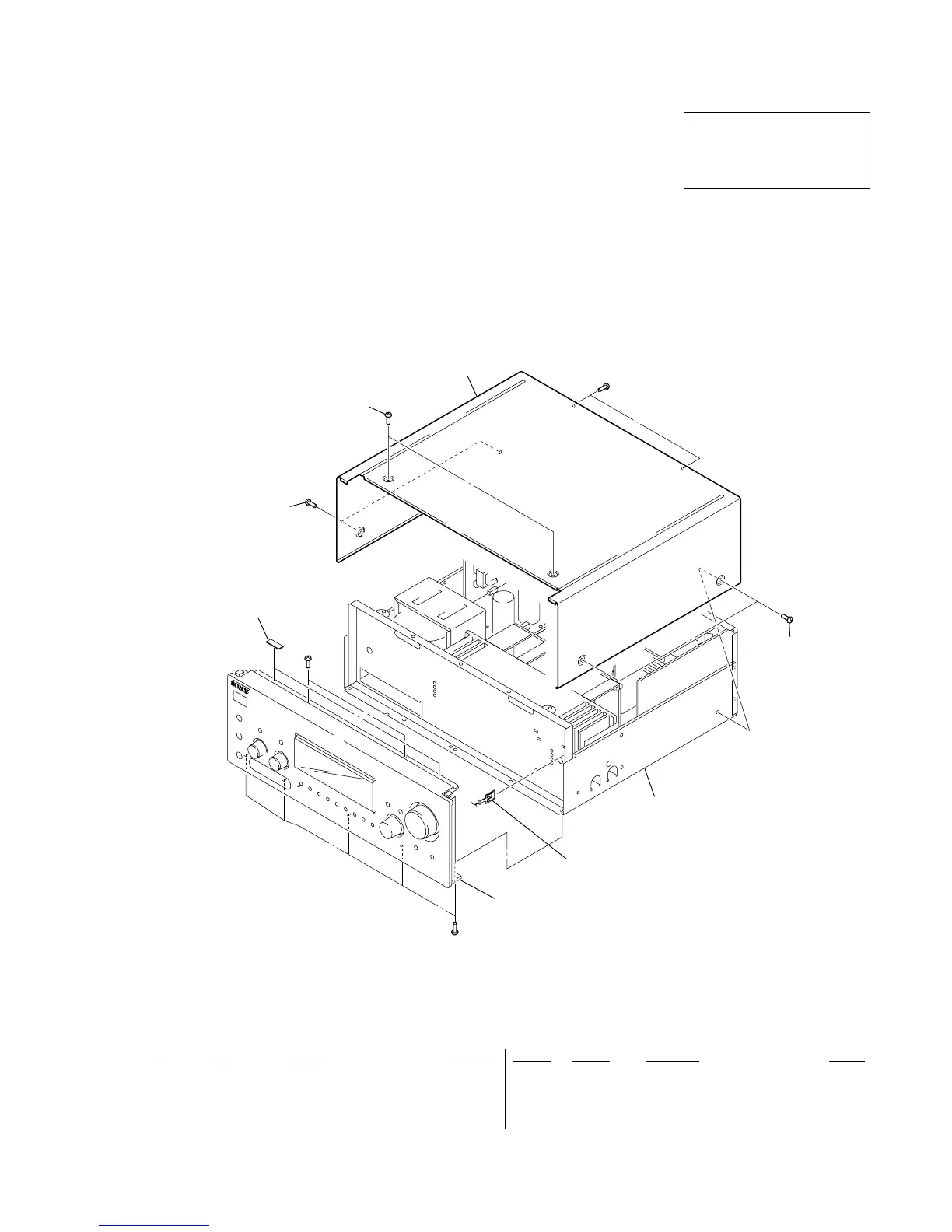
SECTION 7
EXPLODED VIEWS
Ref. No. Part No. Description Remark
Ref. No. Part No. Description Remark
13-314-057-01 CUSHION
24-227-843-03 SCREW (TP), FLAT HEAD (for BLACK)
24-227-843-31 SCREW (TP), FLAT HEAD (for SILVER, GOLD)
34-248-594-21 CASE (414535) (GOLD)
3 4-248-594-41 CASE (414535) (SILVER)
3 4-900-512-02 CASE (414535) (BLACK)
#1 7-685-646-79 SCREW +BVTP 3X8 TYPE2 IT-3
7-1. OVERALL SECTION
• Items marked “*” are not stocked since they
are seldom required for routine service. Some
delay should be anticipated when ordering
these items.
• The mechanical parts with no reference
number in the exploded views are not supplied.
• Accessories are given in the last of the
electrical parts list.
NOTE:
• -XX and -X mean standardized parts, so they
may have some difference from the original
one.
• Color Indication of Appearance Parts
Example:
KNOB, BALANCE (WHITE) . . . (RED)
↑↑
Parts Color Cabinet's Color
• Abbreviation
TW : Taiwan model
1
2
2
2
3
#1
#1
front panel section
back panel section
not supplied
#1
The components identified by mark
0 or dotted line with mark 0 are
critical for safety.
Replace only with part number
specified.