1
SERVICE MANUAL
Canadian Model
AEP Model
UK Model
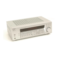
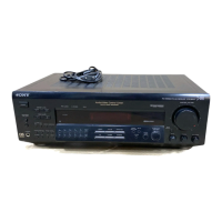
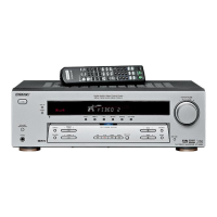
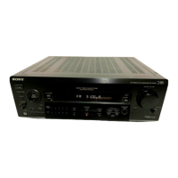
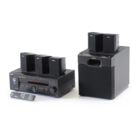
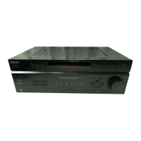
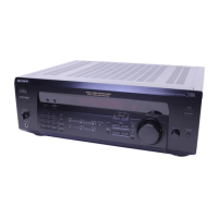
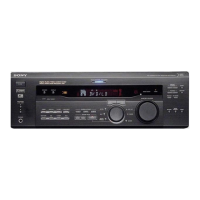
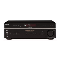
STR-DE585
FM STEREO/FM-AM RECEIVER
AUDIO POWER SPECIFICATIONS
Amplifier section
POWER OUTPUT
Models of area code Canadian
Rated Power Output at Stereo Mode
(8 ohms 40 Hz – 20 kHz, THD 0.09 %)
100 W + 100 W
Reference Power Output
(8 ohms 1 kHz, THD 0.7 %)
FRONT
1)
: 100 W/ch
CENTER
1)
: 100 W
SURR
1)
: 100 W/ch
Models of area code AEP, UK
Rated Power Output at Stereo Mode
(8 ohms 1 kHz, THD 0.7 %)
100 W + 100 W
2)
Reference Power Output
(8 ohms 1 kHz, THD 0.7 %)
FRONT
1)
: 100 W/ch
CENTER
1)
: 100 W
SURR
1)
: 100 W/ch
1) Depending on the sound field settings and the
source, there may be no sound output.
2) Measured under the following conditions:
Area code Power requirements
AEP, UK 230 V AC, 50 Hz
SPECIFICATIONS
Frequency response
MULTI CH IN, CD, 10 Hz – 50 kHz
MD/TAPE, DVD/LD, +0.5/–2 dB (with sound
VIDEO 1, 2 field, and tone bypassed)
Inputs (Analog)
MULTI CH IN, CD, Sensitivity: 250 mV
MD/TAPE, DVD/LD, Impedance: 50 kilohms
VIDEO 1, 2 S/N
3)
: 96 dB
(A, 250 mV
4)
)
3) INPUT SHORT (with sound field and tone
bypassed).
4) Weighted network, input level.
Inputs (Digital)
DVD/LD (Coaxial) Sensitivity: –
Impedance: 75 ohms
S/N: 100 dB
(A, 20 kHz LPF)
VIDEO 2 (Optical) Sensitivity: –
Impedance: –
S/N: 100 dB
(A, 20 kHz LPF)
Outputs
MD/TAPE (REC Voltage: 250 mV
OUT), VIDEO1 Impedance: 10 kilohms
(AUDIO OUT)
SUB WOOFER Voltage: 2 V
Impedance: 1 kilohms
Tone
Gain levels: ±6 dB, 1 dB step
Ver 1.0 2002. 04
9-873-966-01
2002D0400-1
© 2002. 04
Sony Corporation
Home Audio Company
Published by Sony Engineering Corporation
Manufactured under license from Dolby Laboratories.
“Dolby”, “Pro Logic” and the double-D symbol are
trademarks of Dolby Laboratories.
“DTS” and “DTS Digital Surround” are registered
trademarks of Digital Theater Systems, Inc.
– Continued on next page –