11
Location and Function of Parts
Chapter 1 Overview
Location and Function of Parts
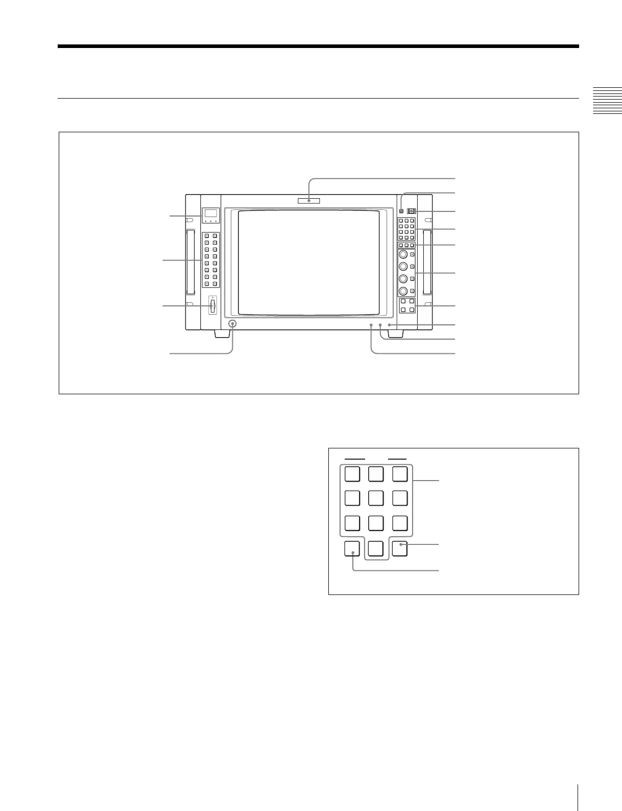
Front Panel
a Tally lamp
With factory settings, the tally lamp lights when pins No. 8
and No. 9 of the PARALLEL REMOTE connector on the
rear panel are shorted. By changing the setting in the
PARALLEL REMOTE menu, different pins on the
PARALLEL REMOTE connector can be used to control
the tally lamp.
For information about the PARALLEL REMOTE menu,
see “
[D]
System Configuration – SYSTEM
CONFIGURATION Menu” on page 39.
b DEGAUSS button
Press to degauss the CRT (every time the monitor is turned
on, the CRT is degaussed automatically). To degauss
again, wait for more than five minutes.
c I/1 switch
Press to turn on the monitor or set it in standby mode. By
setting with the monitor select button, it is possible to turn
on the power of the specified monitors only, or of all
monitors at the same time, or set in standby mode.
For monitor select buttons, see ““Selecting the Monitor/
Group” on page 20.
d Numeric keypad
Use to designate the channel number for the input signal to
be monitored, or to enter the setting values with the menus.
Channel number entry method
When selecting a channel number from 1 to 9, press one-
digit channel number on the numeric keypad.
When selecting a channel number from 10 to 99, press 0
button, then press the two-digit channel number.
1 Tally lamp
8 OPERATE lamp
9 STANDBY lamp
0 OVER LOAD lamp
qd “Memory Stick”
insertion slot
2 DEGAUSS button
3 I/1 switch
4 Numeric keypad
5 Monitor select buttons
7 Menu operation buttons
qa Monitor select
lamps and window
qs Function buttons
6 MANUAL adjustment
buttons and knobs
qf OPTION connector
INPUT
1
2
3
Del
4
5
6
0
7
8
9
Ent
Del button: Deletes the values and
characters entered.
Numeric buttons
Ent button: Confirms the values
and characters entered (ENTER
button of the menu operation
buttons has the same function).