15
Location and Function of Parts
Chapter 1 Overview
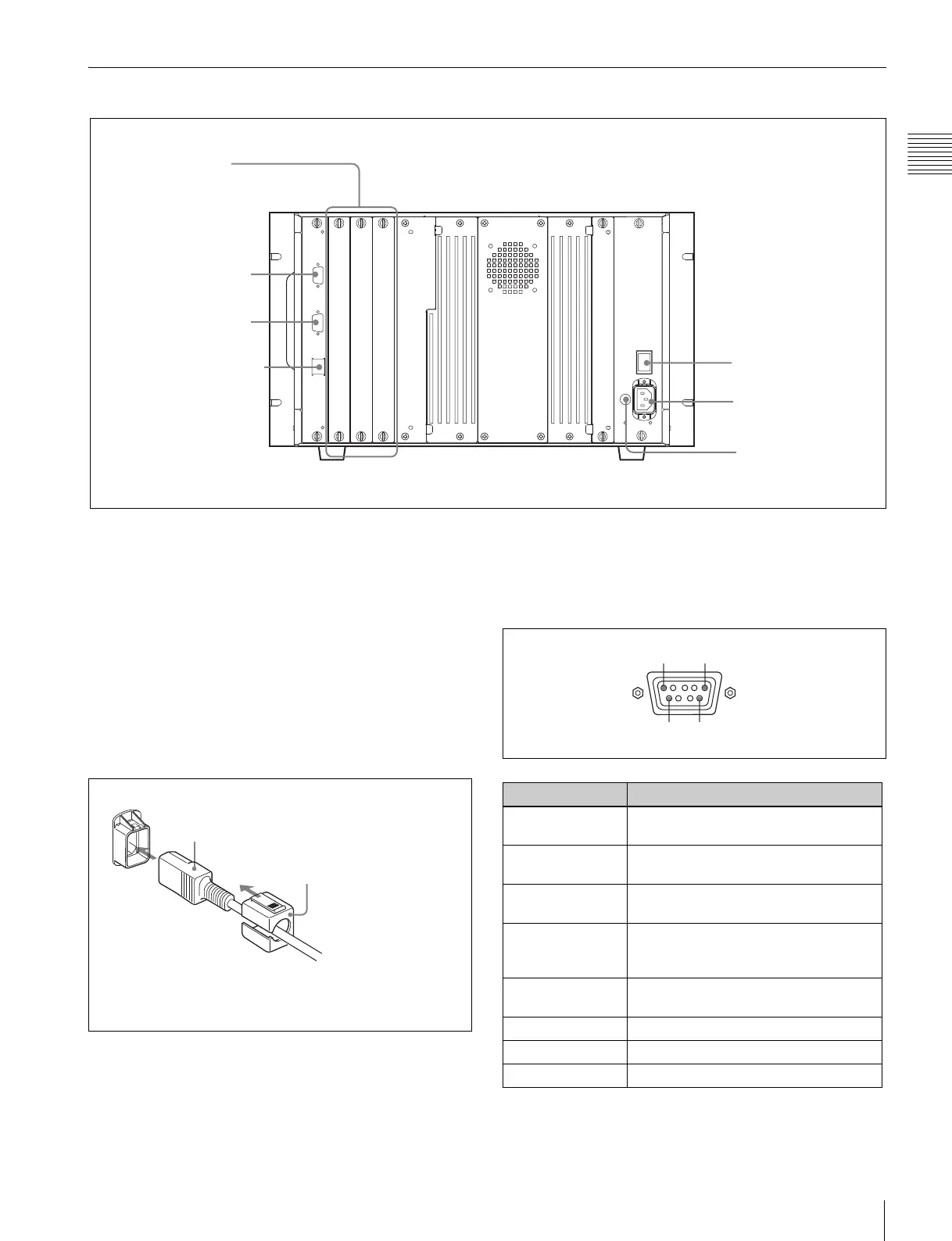
Rear Panel
a MAIN POWER switch
When turned on, the monitor enters operation mode. By
setting in the SYSTEM CONFIGURATION menu, the
monitor can also be set to enter standby mode when the
MAIN POWER switch is turned on.
For information about the SYSTEM CONFIGURATION
menu, see “
[D]
System Configuration – SYSTEM
CONFIGURATION Menu” on page 39.
b AC IN socket (3-pin)
Connects the monitor to an AC power source, via the
supplied AC power cord.
c Fuse
Use a T4AH fuse.
d Input option slots
The monitor may be fitted with optional input adaptors.
e PARALLEL REMOTE connector (female, D-sub
9-pin)
Forms a parallel switch and controls the monitor
externally. The pin assignment and factory setting function
assigned to each pin are given below.
All pin function assignments can be changed with the
PARALLEL REMOTE menu.
1 MAIN POWER switch
2 AC IN socket
4 Input option slots
5 PARALLEL REMOTE
connector
6 SERVICE connector
7 LAN (10/100) connector
3 Fuse
AC power cord (supplied)
AC Plug holder (supplied)
Attach the AC Plug holder to the AC power cord, and connect
it to the AC IN socket so that the cord does not come loose.
Pin number Function
1 Set input signal channel 1 (numeric
keypad function)
2 Set input signal channel 2 (numeric
keypad function)
3 Select sync signal (SYNC button
function)
4 Set the screen to monochrome, or set
for automatic switching based on the
input signal (MONO button function)
5 Marker (set in the channel) ON/OFF
(MARKER button function)
6, 7 Not connected
8 Tally lamp ON/OFF
9Ground
15
96