1-8
VPL-ES5/EX5/EX50/EX5U/EW5
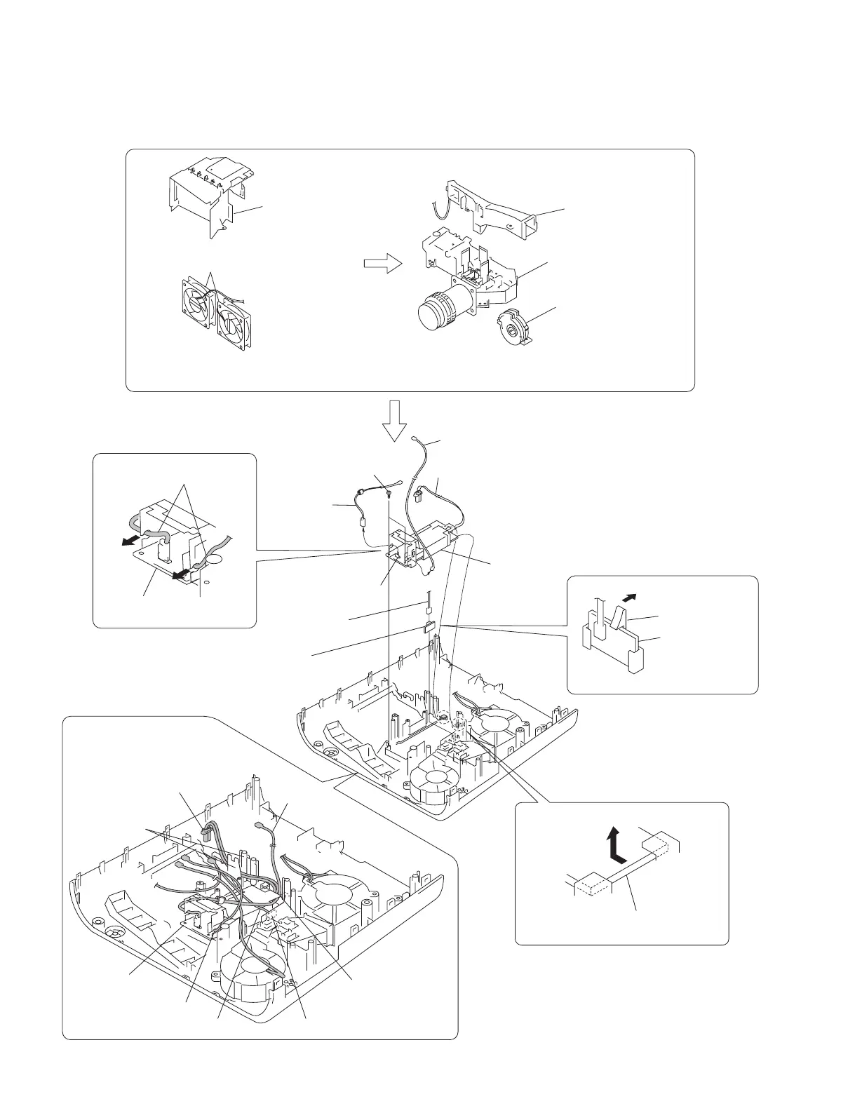
1-3-9. Lamp Power Supply
6
Two tapping screws
(PAN 3 x 7)
9
Lamp power supply
8
Remove the lamp power supply
in the direction of the arrow
E
.
0
Claw
!-
Door detection
switch board
Caution :
When re-assembling the machine,
route the respective harnesses and
wires at the specified locations as shown.
7
Two
harnesses
Door detection
switch board
CN1
P1
A
C
E
A
B
C
B
D
D
2
Fan (Exhaust)
*2 80*25 170MM AD0812UB/HB
(Refer to section 1-3-8, steps 2 to 8.)
1
Lamp box assembly
3
Duct lamp assembly
4
Focus/Zoom adjust
assembly
5
Optical unit assembly
Lamp power supply
Lamp power supply
Door detection switch board
(Refer to section 1-3-6, steps 5 to 10) and
(refer to section 1-3-7, steps 1 to 6.)
Route the harness
A
underneath this sheet.
Route the harness
D
between them.