1-4
VPL-ES5/EX5/EX50/EX5U/EW5
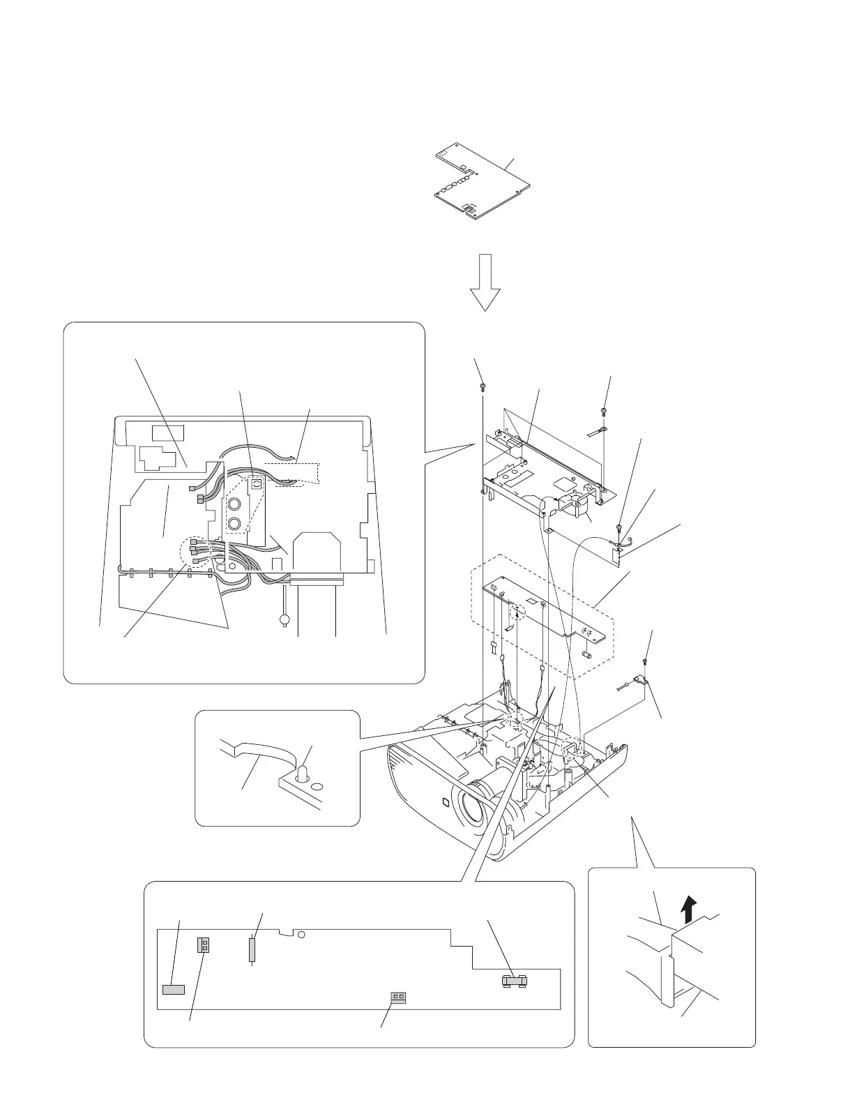
1-3-4. Power Board and Thermal Sensor Board
5
Screw
(+PSW M4 x 6)
6
Four tapping screws
(PAN 3 x 7)
2
Tapping screw
(PAN 3 x 7)
3
Clamp
4
Sheet
!=
Tapping screw
(PAN 3 x 7)
8
MB bracket
![
Thermal sensor board
!-
Power board
9
Remove the three connectors.
Duct lamp assembly
Fuse (H.B.C.)
(F601)
Miniature fuse-links (F602)
CN603
CN605
CN701
0
Dowel
Power board
Power board
Duct lamp assembly
7
Remove the fan in the
direction of the arrow.
J1
1 Mai
n board
(Refer to section 1-3-3, steps 2 to 6.)
Fan
Caution :
When attaching the MB bracket, bind the five harnesses into the shape
of
“
U
”
and attaching them to the MB bracket.
Duct lamp assembly
Be careful that the harnesses must not override on
top of this port or must not be pinched by this portion.
Check to see that the seven connectors are
protruding from the MB bracket.