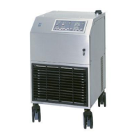
Heater-Cooler System 3T • System description
CP_IFU_16-XX-XX_USA_015 3.3
Item Designation Function
1 Mains power switch ➜ Powering the heater-cooler up/down
➜ Integrated automatic cutout
2 Control panel ➜ For separated operation and
configuration of the two functional
groups (3 water circuits)
– patient circuits and
– cardioplegia circuit
3 Filler neck with cover ➜ For filling all tanks with filtered tap
water.
4 CAN-Bus connector with cover
5 Outlet patient circuit 2
with venting valve
➜ All inlets and outlets with fast
(Hansen-type) connectors 1/2"
6 Inlet patient circuit 2
7 Outlet patient circuit 1
with venting valve
8 Inlet patient circuit 1
9 Outlet cardioplegia circuit
with venting valve
10 Inlet cardioplegia circuit
11 Drain valve of the patient circuits
➜ Emptying of the tanks
12 Drain valve of the cardioplegia circuit
13 Overflow outlet
14 Overflow bottle (with tubing) ➜ For collecting the excess water
(during filling)
15 Fan
➜ Ventilation of the heater-cooler
16 Ventilation grill
17 Potential equalization point ➜ Connection of the potential
equalization cable
18 Power cable ➜ Power supply of the heater-cooler
19 Castors ➜ Front castors with brakes
20 Bumper Mounting upon delivery (by Sorin service
staff).