Heater-Cooler System 3T • System description
3.4 CP_IFU_16-XX-XX_USA_015
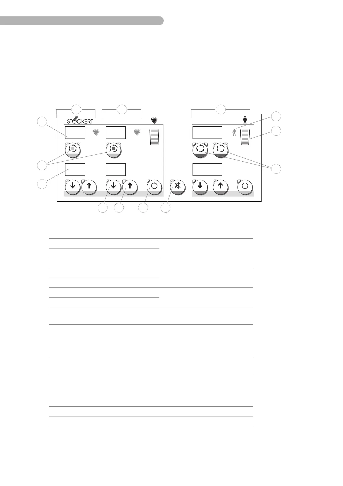
3.2.2 Overview - control panel
The control panel manages all control and monitoring functions of the heater-cooler. These are:
◗ Adjusting the set values,
◗ Starting and stopping the pumps,
◗ The display of all set and actual temperatures,
◗ The display of the water level and the alarm.
Fig. 2: Control panel
°C °C °C
°C °C °C
1 2
36.8
36.838
37
7
5
24
25
21 22 23
33
32
26 27 28 29
30
31
Item Designation Function
21 Cardioplegia cooling circuit elements
➜ Displays and controls all settings of
the individual circuits
22 Cardioplegia heating circuit elements
23 Elements of the patient circuits
24 7-segment displays Actual temperatures
➜ Displays the actual and the set
temperatures
25 7-segment displays Set temperatures
26 Keys Lower set temperature
➜ for increasing and/or decreasing the
set value gradually (in steps)
27 Keys Raise set temperature
28 Keys Standby ➜ Switching on and off the functional
group (standby mode)
29 Key Audio alarm off ➜ Switches off the audio alarm (in case
of alarm) for a maximum of 2 minutes,
press the key again to switch the
alarm back on.
30 Keys Circuit Start/Stop
(patient circuits)
➜ Starting and stopping the circuit in
question individually.
31 Keys Circuit Start/Stop
(cardioplegia circuit)
heating tank: red dot
cooling tank: blue dot
➜ Starting and stopping the circuit as
well as switching between the
heating and the cooling tanks.
32 Bar graph display Water level ➜ Display of the water level
33 Display Alarm ➜ Red LED lights up in case of alarm
 Loading...