Heater-Cooler System 3T • Operation
5.12 CP_IFU_16-XX-XX_USA_015
The patient circuits
The two patient circuits are supplied with water via two separate pumps (from a common tank).
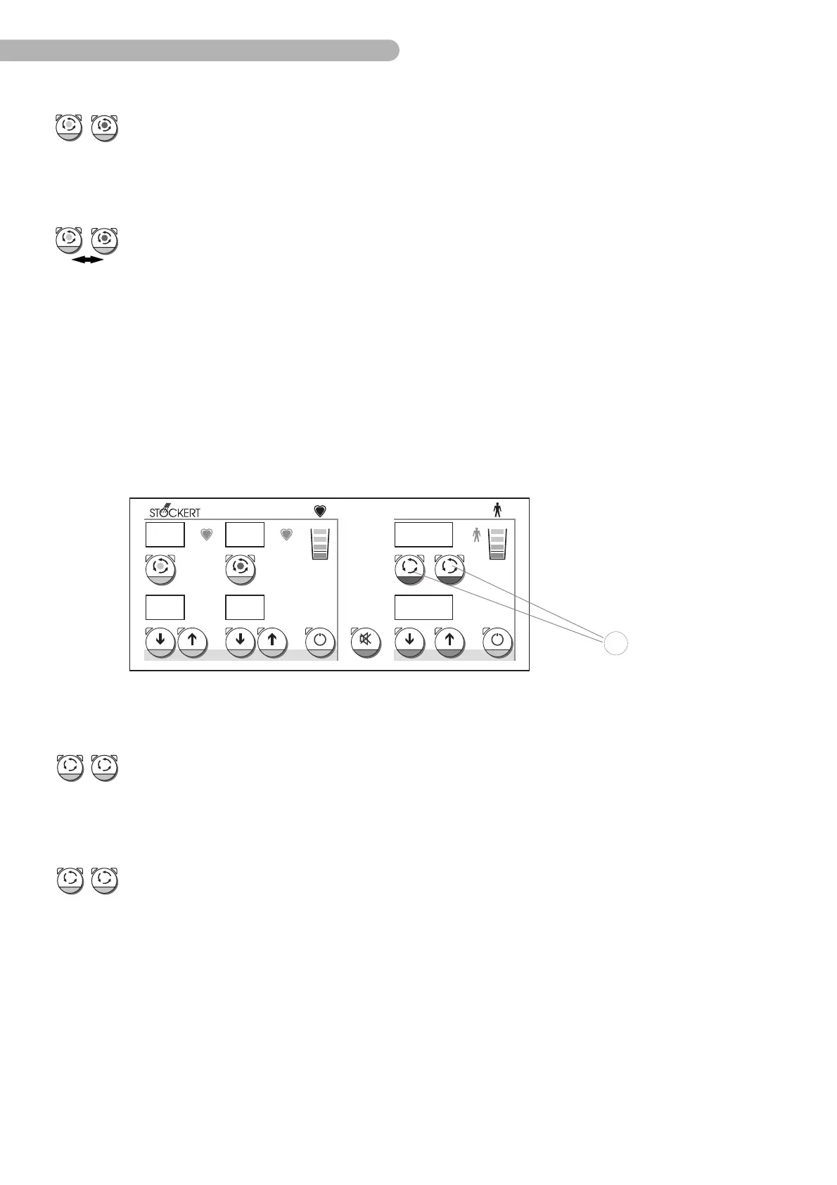
Fig. 16: Starting/stopping the patient circuit
Stopping the cardioplegia circuit
Press the key Circuit Start/Stop a second time to stop the active circuit.
➜ The water supply is stopped.
➜ The green LEDs on the key are inactive.
Switching between the cardioplegia circuits
Press the key Circuit Start/Stop
of the circuit which is inactive at present.
➜ Now, the selected tank supplies the circuit. This changeover takes about 5 seconds.
➜ The green LEDs on the key flash (alternatingly on the heater-cooler).
When activating the cardioplegia cooling circuit, it automatically has priority over the
patient circuits. As a consequence, the cooling performance of the patient circuits is
significantly reduced. Therefore, deactivate the cardioplegia cooling circuit at once, as
soon as it is no longer required.
!
°C °C °C
°C °C °C
1 2
37.6
20.1 20
37
7
5
Starting the patient circuit
Press the key Circuit Start/Stop 30 on the heater-cooler to start the required circuit.
➜ The pump of the selected circuit starts running.
➜ The green LEDs of the key flash (alternatingly on the heater-cooler).
Stopping the patient circuit
Press the key Circuit Start/Stop again to stop the activated circuit.
➜ The pump of the selected circuit stops.
➜ The green LEDs of the key have stopped flashing.
21