Scorpio User Guide
33
POWERING THE SL-2
The SL-2 is powered by the Scorpio via the Expansion Port. No addi-
tional power source is needed to power the SL-2.
To activate the SL-2, set the System>Expansion Port menu to On.
Save power when the SL-2 is not in use by setting the Expansion Port
menu to Off. When the Expansion Port is set to Off, the SuperSlot
menu is grayed out.
ROUTING SL-2 SOURCES TO CHANNELS
The SL-2 has a total of 12 sources, up to eight channels of wireless
from the two slots (A1-A4, B1-B4) plus four channels of AES from the
rear panel TA3 ports. Only eight of these sources can be used at any
one time. AES 3 and 4 cannot be selected when a slot receiver output
is analog.
To route an SL-2 Source to a channel, access a channel’s source
screen and select from A1-A4, B1-B4, AES 1-4. When A1-A4, B1-B4
are selected as source, use the */** toggle as a shortcut to the
selected receiver’s setup screen.
For SL-2 A1-A4, B1-B4, and AES 1-4 sources, channel trim gain range
is -20 to 50 dB.
When the A10-RX is receiving signal from the A20-Mini, the trim gain
of the associated 8-Series channel is 0 to 60 dB. See GainForward.
RF OVERLOAD LEDS Each antenna input on the front panel of the
SL-2 has an associated LED that displays incoming RF level status.
Red = approaching RF overload threshold of the SL-2
Orange = approaching overload threshold of digital wireless systems
Off = no overload
To disable the LEDs go to SL-2 Options>Antenna LEDs and set to Off.
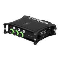
SL-2 RECEIVER OVERVIEW Select the SuperSlot menu to enter
the SL-2 Receiver Overview screen which displays information for all
receivers connected to the SL-2. Hold Meter then press the HP knob
to quickly access the Receiver Overview screen.
A1-A4, B1-B4 Use the Select knob to scroll and select an SL-2
channel to access the individual Receiver Setup screen. See Receiver
Setup Screen for more details.
POST-TRIM CHANNEL METERING Displays the post-trim audio
level of the Scorpio channel receiving audio from the SL-2 source.
When the SL-2 source is not routed to a Scorpio channel, no signal is
displayed on the meters.
RF FREQUENCY Displays the frequency of the receiver in MHz.
TRANSMITTER BATTERY LEVEL Displays the battery level of the
paired transmitter, if applicable.
Green = over 50%
Yellow = over 20%
Orange = over 10%
Red = less than 10%.
TRANSMITTER RECORD STATUS Indicates the record status of the
paired transmitter, if applicable. Red = recording
TRANSMITTER STATUS BOX (A10-RX only)
A10-TX: Indicates paired transmitter Mute, Limiter, and Audio Over-
load status.
A20-Mini: Indicates paired transmitter Mute status. The Limiter and
Audio Overload indicator are displayed for the 8-Series channel receiv-
ing the A20-Mini signal.
Blue with ‘M’ = Transmitter Mute On
Yellow with ‘L’ = Limiting
Red with ‘O’ = Audio Overload
RF LEVEL HISTORY Displays the RF level over a period of time.
Duration of RF History is set in SL-2 Options>RF History Duration pa-
rameter from 30 to 600 seconds in 10 s steps, default duration is 30
seconds. The taller the green bar, the healthier the received RF signal.
A red bar signies receiver RF overload (A10-RX only).

 Loading...