Page. 44 of 87
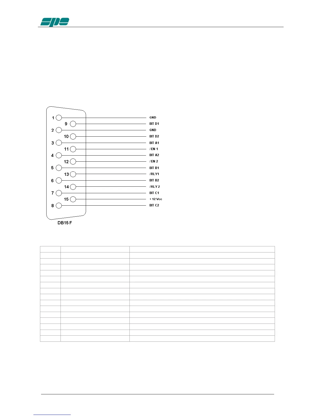
13.4 AUX Connector
This connector provides data about the bands currently being switched on both INPUTs,
indicating which input is connected to the antenna ANT 1/2/3/4 and which is connected
to the SO2R socket.
In this way you can know which one of the two transceivers is currently
connected to the switched output antenna and when it is in transmission etc.
INPUT 1 0 = not connected with ANT, 1 = connected with ANT
INPUT 1 0 = TX state 1 = RX state
INPUT 2 0 = not connected with ANT, 1 = connected with ANT
INPUT 2 0 = TX state 1 = RX state
Each output is an open collector.
Note: WARNING, SPE is not responsible for any failure resulting from misuse of hardware
interfaces.