BAA
B
NYLON ICR TUBE
CHAINSTAY
CHAINSTAY
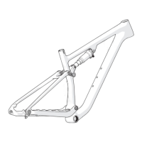
FRAME FRAME
3
2
1
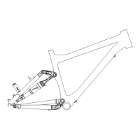
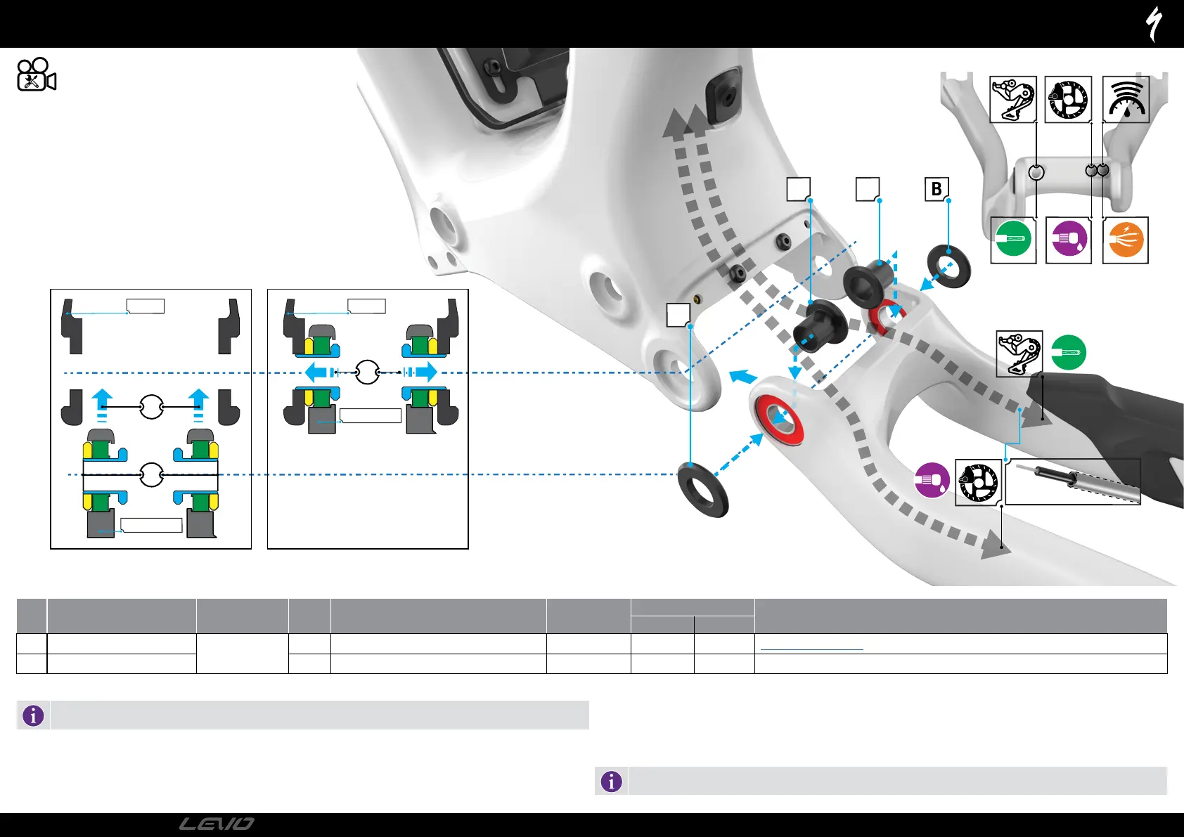
MOTOR MAIN PIVOT ASSEMBLY
# PART NAME PART NUMBER QTY SPEC TOOL
TORQUE
COMMENT
Nm in-lbf
A Main Pivot Sleeve
S210500012
2 10 mm ID x 21 mm OD x 3 mm W, S-Steel N/A N/A N/A Part of Suspension Bolt Kit
B Main Pivot Spacer 2 12 mm ID x 23 mm OD x 3 mm W, Alu N/A N/A N/A
ROUTE THE GUIDE TUBES INTO THE FRONT TRIANGLE
Before installing the motor, assemble the rear triangle to the front triangle.
Route the guide tube assembly from the motor housing, up though the side-arm exiting the non-drive side ICR port at the head tube.
Place the guide cover and insert the screw, then tighten to specification.
Place the spacers (B) against the bearings on the main pivot.
REAR TRIANGLE TO FRONT TRIANGLE ASSEMBLY
1: Insert the pivot sleeves (A) through the main pivot bearings and spacer.
2: Insert the chainstay into the frame and align the pivot holes.
3: Push the pivot sleeves through the frame to hold the rear triangle in place.
Assemble the motor into the frame.
The main pivot sleeves can be inserted from the inside to hold the rear triangle in place while you install the motor.
PAGE 11
2022
TECHNICAL GUIDE