30
sec
<
1
5
3
4
2
2
6
8
D
B
A
C
7
CUT
TAB
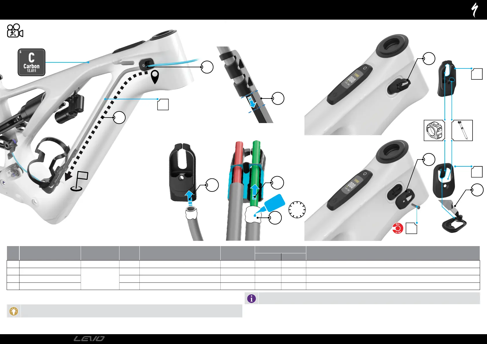
DROPPER HOUSING GUIDE TUBE
1: Glue one end of the guide tube into the ICR guide base (B) with a small drop of glue (Loctite 416) to one end of the guide tube (1).
2: Briefly allow the glue to spread around the guide tube, then quickly insert them into the ICR guide hole (2).
TECH TIP: Loctite 416 has a 20-30 second work time. Ensure the guide tube is completely inserted into the ICR guide. Failure
to do so will cause housings to snag.
3: Insert the other end of the guide tube firmly into the end of the dropper housing guide . Make sure the tube is completely inserted into the
dropper housing guide. Failure to do so will cause housings to snag.
Orientate the ICR guide and the dropper housing guide 90 degrees to each other before gluing. The face of the ICR guide
base should point to the right of the dropper housing guide.
4: Insert the dropper housing assembly through the ICR port located in the drive side head tube area.
5: Slide the assembly down the down tube 6: Locate the ICR guide in the port in the drive side head tube.
7: Cut the tab from the guide cover to allow for the remote cable to pass through.
8: Place the ICR guide and cap into the frame. then torque to specification (7)
# PART NAME PART NUMBER QTY SPEC TOOL
TORQUE
COMMENT
Nm in-lbf
A Nylon Guide Tube 1 N/A N/A N/A
S1 - 385 mm | S2 - 395 mm | S3 - 410 mm | S4 - 430 mm | S5 - 465 mm | S6 - 480 mm
B ICR Guide Base
S216500007
1 N/A N/A N/A
C ICR Guide Cover, 2 Wires x 2 Cables 1 2 Wires 2 Cables N/A N/A N/A Cut the tab off of the guide cover to access the slot on the guide base for the remote connector insertion.
D ICR Guide Screw M3 x 18 mm x 0.5 mm p Steel TX10 0.8 7
PAGE 2
2022
TECHNICAL GUIDE