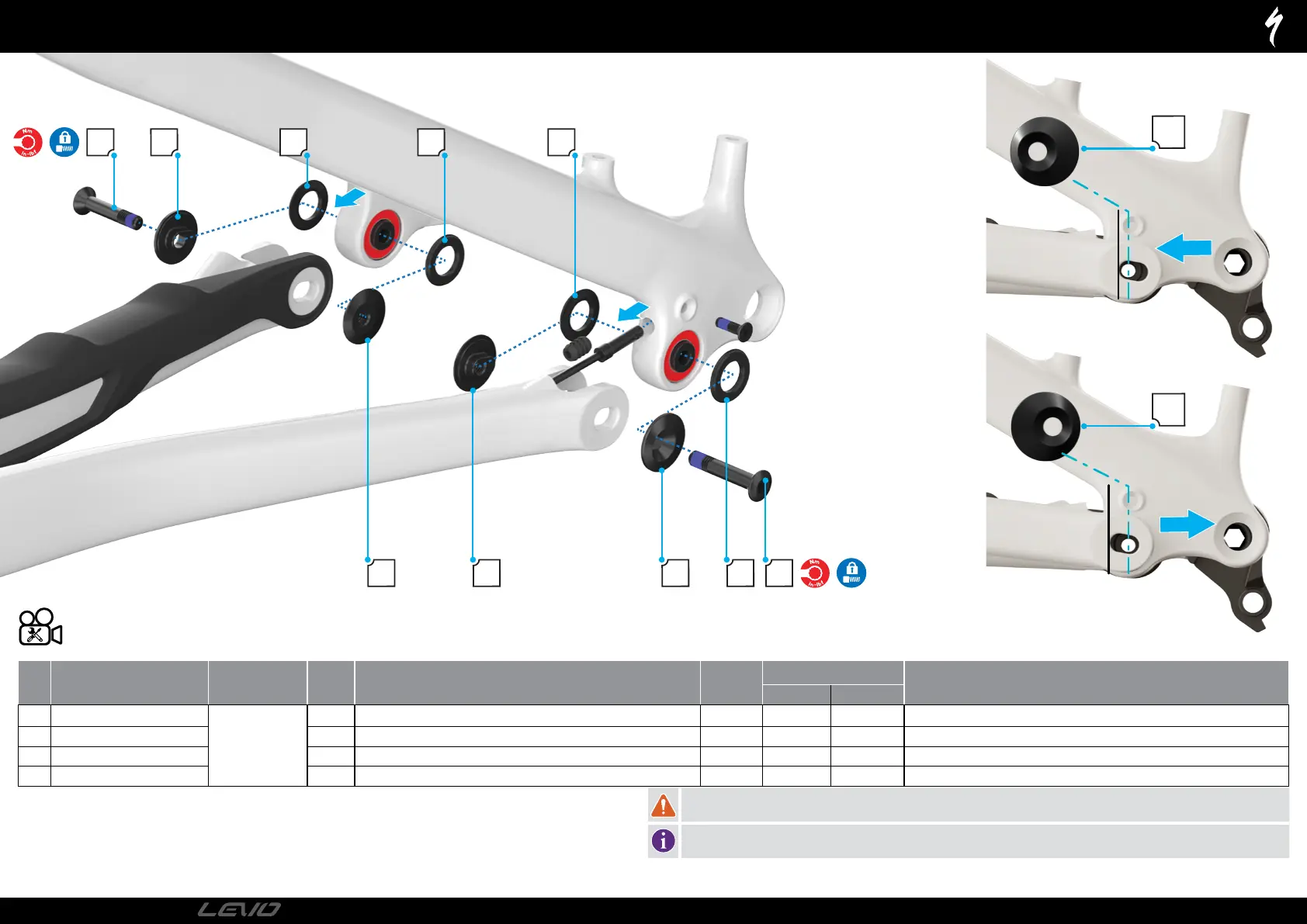
LOW
HIGH
B B C DA
D C A A A
C
C
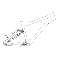
HORST FLIP CHIP
# PART NAME PART NUMBER QTY SPEC TOOL
TORQUE
COMMENT
Nm in-lbf
A Pivot Spacers
Part Of Suspension
Bolt Kit
S210500012
4 12 mm ID x 21 OD mm x 2.5 mm thk N/A N/A N/A
B Geo Adjust Pivot Spacer Nut 2 Inside Spacer M6 x 1.0 mm p N/A N/A N/A
C Geo Adjust Pivot Space 2 Outside Spacer 6mm ID N/A N/A N/A
D Pivot Bolt 2 M6 x 32.5 mm x 1.0 mm p Steel BLK 5 mm hex 10 90
INSTALLATION PROCESS:
Place the pivot spacers against the bearing with the tapered side against the bearing.
Align the chainstay pivot hole with the seatstay pivot hole.
Insert the flip chips located in either the high or low position.
Grease the non-threaded surfaces of the bolts, insert them, then torque to specification.
WARNING: The drive side and non-drive side Horst flip chips must both be aligned in the same high or low position. Improperly
installed Horst flip chips can damage the frame and can also cause you to lose control and fall.
All models are assembled with the flip chips in the high position. Switching to the low position lowers the bottom bracket height
by approximately 7 mm and slackens the head tube angle by approximately 0.5 degrees.
PAGE 25
2022
TECHNICAL GUIDE