Maintenance Waukesha Cherry-Burrell
Page 40 95-03080 12/2010
20. Install the original shims on the motor adapter shaft.
21. Install the backplate with the seal assembly and impeller on
the motor shaft.
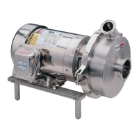
22. Check the impeller/backplate clearance with the backplate
held firmly in position against motor adapter. Check the
space between the back of the impeller and the backplate
with a feeler gauge (.030 nominal) while holding the back-
plate tight against the bearing housing flange. (Any axial
mo
vement of the shaft should not be added to the .030 nomi-
nal clearance). See Figure 44.
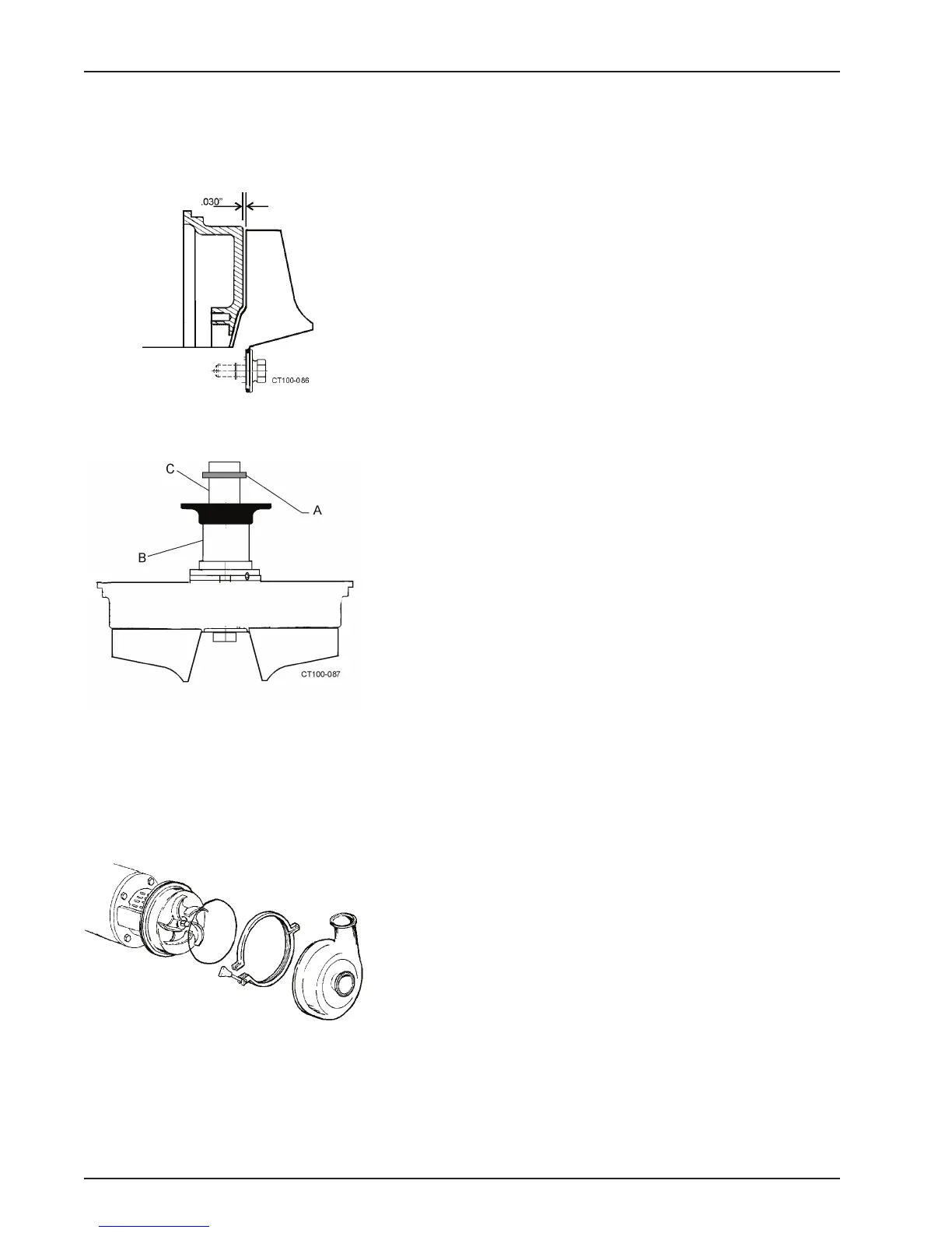
23. If needed, change this clearance by adding or removing
shims. Shims (Figure 45, itemA) can be added on the drive
shaft (Figure 45, item C) behind the impeller shaft (Figure 45,
item B).
24. Confirm operating clearances by cla
mping the casing to the
bearing housing flange and rotating the shaft/impeller manu-
ally to be sure the impeller does not touch the casing or back-
plate.
25. Tighten the set screws in the spring retainer through the 1/4
NPT ce
nter port in flush housing (Figure 41, item N).
26. Insert the plug in the port and tighten.
27. Remove the backplate/impeller assembly, apply anti-seize or
equal compound to the mot
or shaft, and install the key.
28. Install the backplate/impeller assembly and lock it in place
usin
g the o-ring and impeller retainer bolt.
29. Install the casing o-ring on the backplate and clamp the cas-
ing in place. See Figure 46.
NOTE: Rotate the impeller
manually to ensure that it does not rub
on the backplate or casing.
Figure 44 - Clearance Between Impeller
and Backplate
Figure 45 - Locations of Shims
Figure 46 - Install Casing