Reset control AN2752
16/42 Doc ID 14651 Rev 3
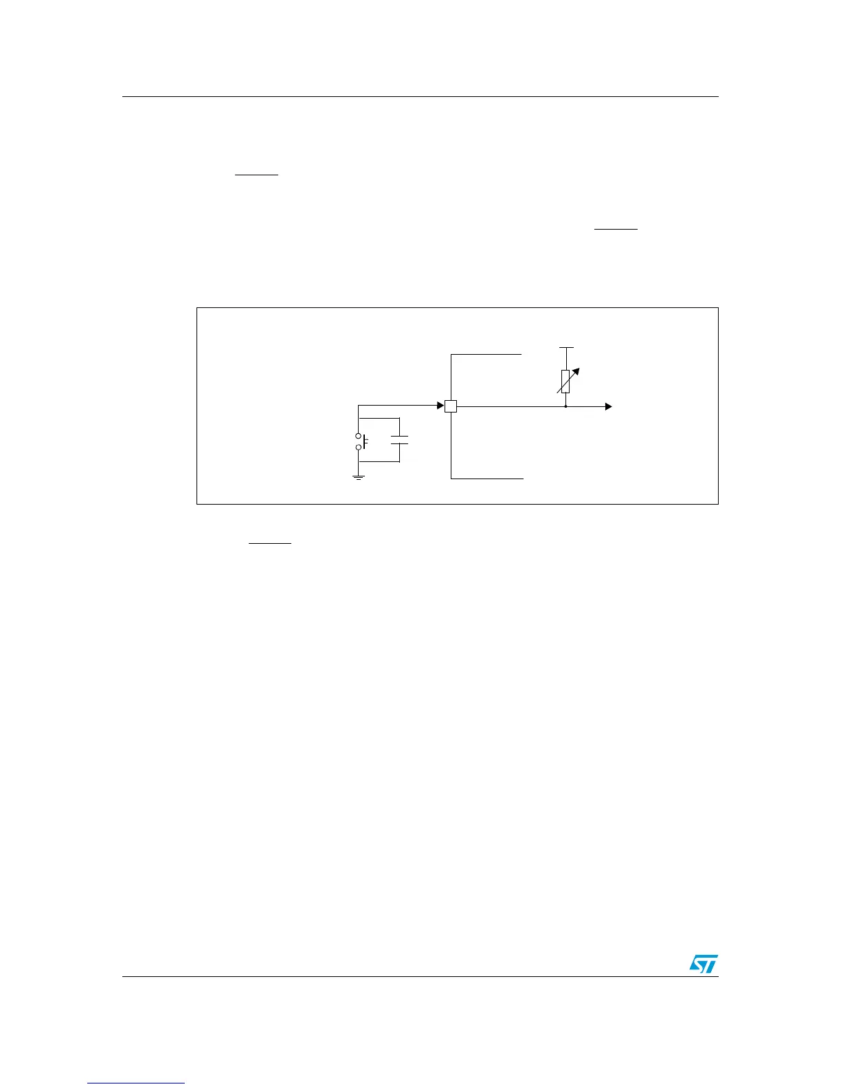
5.2.1 RC circuit
The RC circuit concept is the simplest and most cost-effective external reset solution, where
the supply waveform is monotonous and the maximum rise time is known. The principle is to
let the RESET
pin rise with the microcontroller supply voltage after a delay. The circuit is
shown in Figure 10.
The basic solution is to use an RC delay determined by the rise rate of the supply itself. The
component values must be chosen to create enough delay to keep the RESET
pin below the
V
IL
specification until V
CC
reaches a safe operating voltage. Normally, a delay (time
constant) corresponding to at least 30 % of the total rise time is advised.
Figure 10. RC circuit
The RC circuit scheme requires a certain delay between a power-down and the next power-
up, because the delay generator has to be reinitialized. In practice, a pull-down capacitor
between RESET
and V
SS
needs to be discharged.

 Loading...


