Power supply AN2752
8/42 Doc ID 14651 Rev 3
2.2 Main operating voltages
STM8S devices are processed in 0.13 µm technology. The STM8S core and I/O peripherals
need different power supplies. In fact, STM8S devices have an internal regulator with a
nominal target output of 1.8 V.
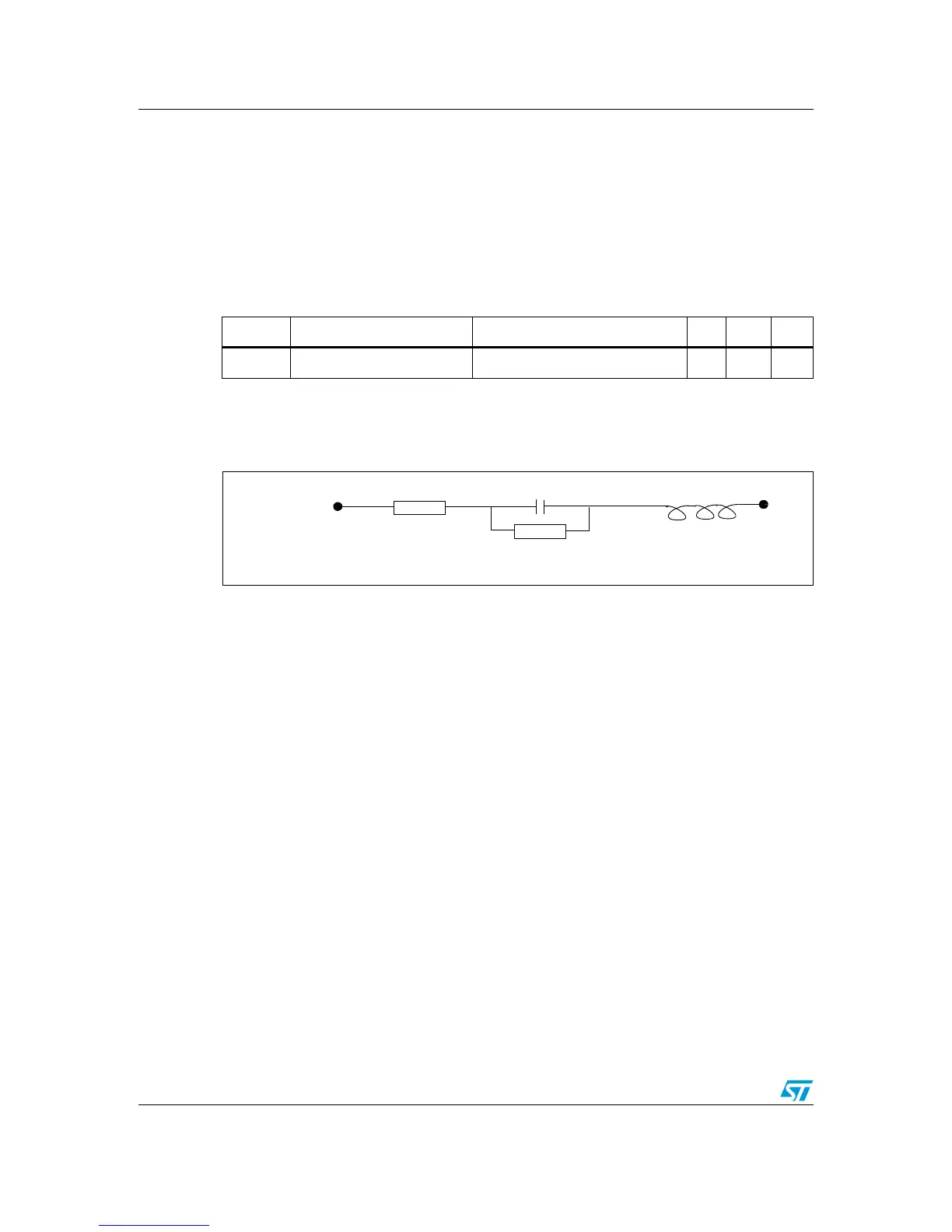
Stabilization for the main regulator is achieved connecting an external capacitor C
EXT
to the
V
CAP
pin. C
EXT
is specified in Ta bl e 1. Care should be taken to limit the series inductance to
less than 15 nH.
Figure 2. External capacitor
2.3 Power-on/power-down reset (POR/PDR)
The input supply to the main and low power regulators is monitored by a power-on/power-
down reset circuit. The monitoring voltage range is 0.7 V to 2.7 V.
During power-on, the POR/PDR keeps the device under reset until the supply voltages (V
DD
and V
DDIO
) reach their specified working area.
At power-on, a defined reset should be maintained below 0.7 V. The upper threshold for a
reset release is defined in the electrical characteristics section of the product datasheet.
A hysteresis is implemented (POR > PDR) to ensure clean detection of voltage rise and fall.
The POR/PDR also generates a reset when the supply voltage drops below the V
POR/PDR
threshold (isolated and repetitive events).
Recommendations
All pins need to be properly connected to the power supplies. These connections, including
pads, tracks and vias should have the lowest possible impedance. This is typically achieved
with thick track widths and preferably dedicated power supply planes in multi-layer printed
circuit boards (PCBs).
In addition, each power supply pair should be decoupled with filtering ceramic capacitors (C)
at 100 nF with one chemical C (1..2 µF) in parallel on the STM8S device. The ceramic
capacitors should be placed as close as possible to the appropriate pins, or below the
appropriate pins, on the opposite side of the PCB. Typical values are 10 nF to 100 nF, but
Table 1. General operating conditions
Symbol Parameter Conditions Min Max Unit
C
EXT
V
CAP
external capacitor
(1)
1. Care should be taken when selecting the capacitor, due to its tolerance, as well as its dependency on
temperature, DC bias and frequency in addition to other factors.
0.05 ≤ ESR ≤ 0.2 Ω at 1 MHz 470 1000 nF

 Loading...


