STM8 development tools AN2752
22/42 Doc ID 14651 Rev 3
8 STM8 development tools
Development tools for STM8S microcontrollers include the STice emulation system
supported by a complete software tool package including C compiler, assembler and
integrated development environment with high-level language debugger.
8.1 Single wire interface module (SWIM)
8.1.1 SWIM overview
In-circuit debugging mode or in-circuit programming mode are managed through a single
wire hardware interface based on an open-drain line, featuring ultra fast memory
programming. Coupled with an in-circuit debugging module, the SWIM also offers a non-
intrusive read/write to RAM and peripherals. This makes the in-circuit debugger extremely
powerful and close in performance to a full-featured emulator.
The SWIM pin can be used as a standard I/O (with 8 mA capability) which has some
restrictions if the user wants to use it for debugging. The most secure way to use it is to
provide a strap option on the PCB. Please refer to the STM8 SWIM communication protocol
and debug module user manual (UM0470) for more SWIM protocol details.
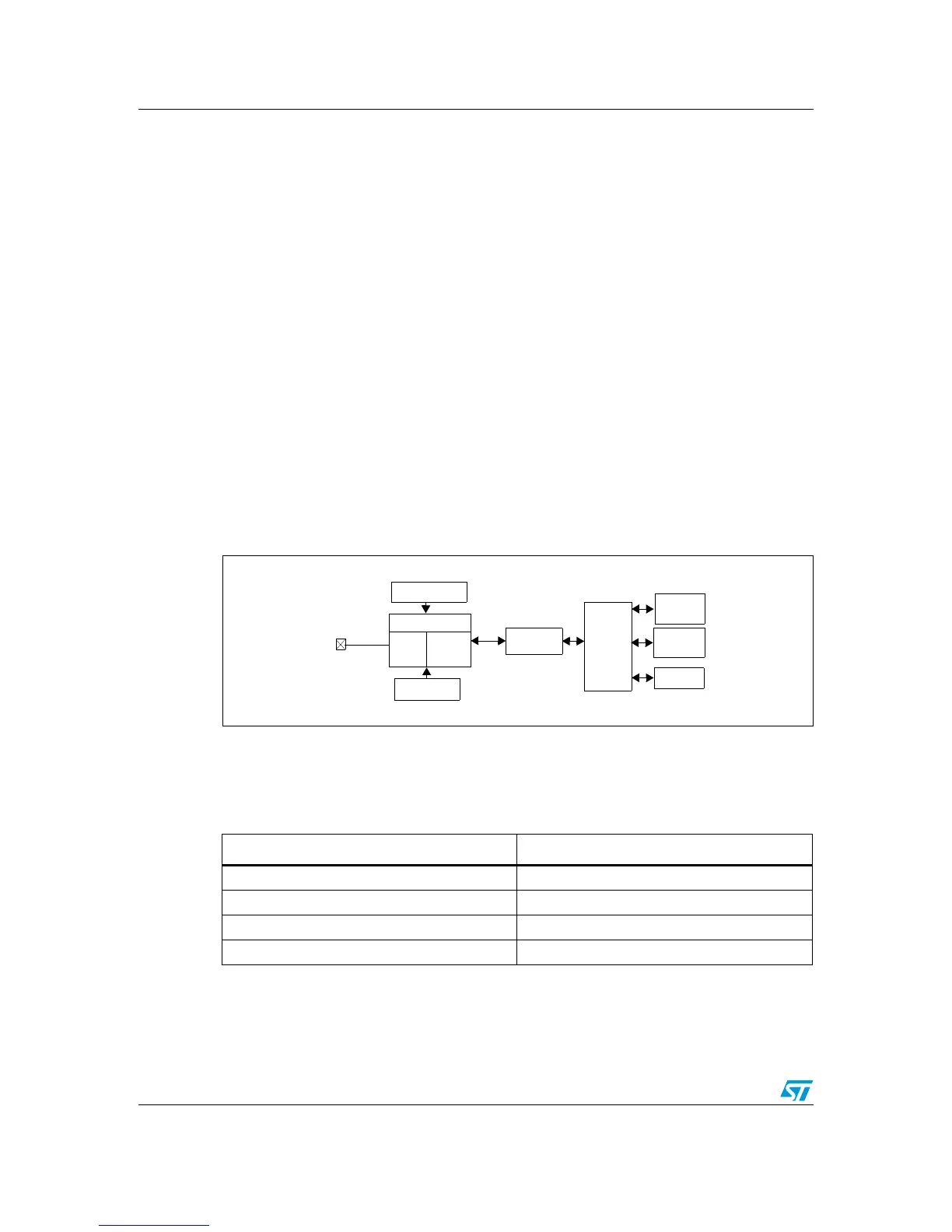
Figure 13. Debug system block diagram
8.1.2 SWIM connector pins
The SWIM connector pins consist of 4 pins as described in Ta bl e 3 .
 Loading...


