Setting up the STM8 development environment AN2752
36/42 Doc ID 14651 Rev 3
10.3.3 Connecting the hardware
The Rlink tool can be connected to the PC by a standard USB connection. It is also powered
by the USB interface.
On the controller side the connection to the STM8 evaluation board is made by the SWIM
interface cable. The STM8 evaluation board is powered by an external 5 V supply (see
Figure 25).
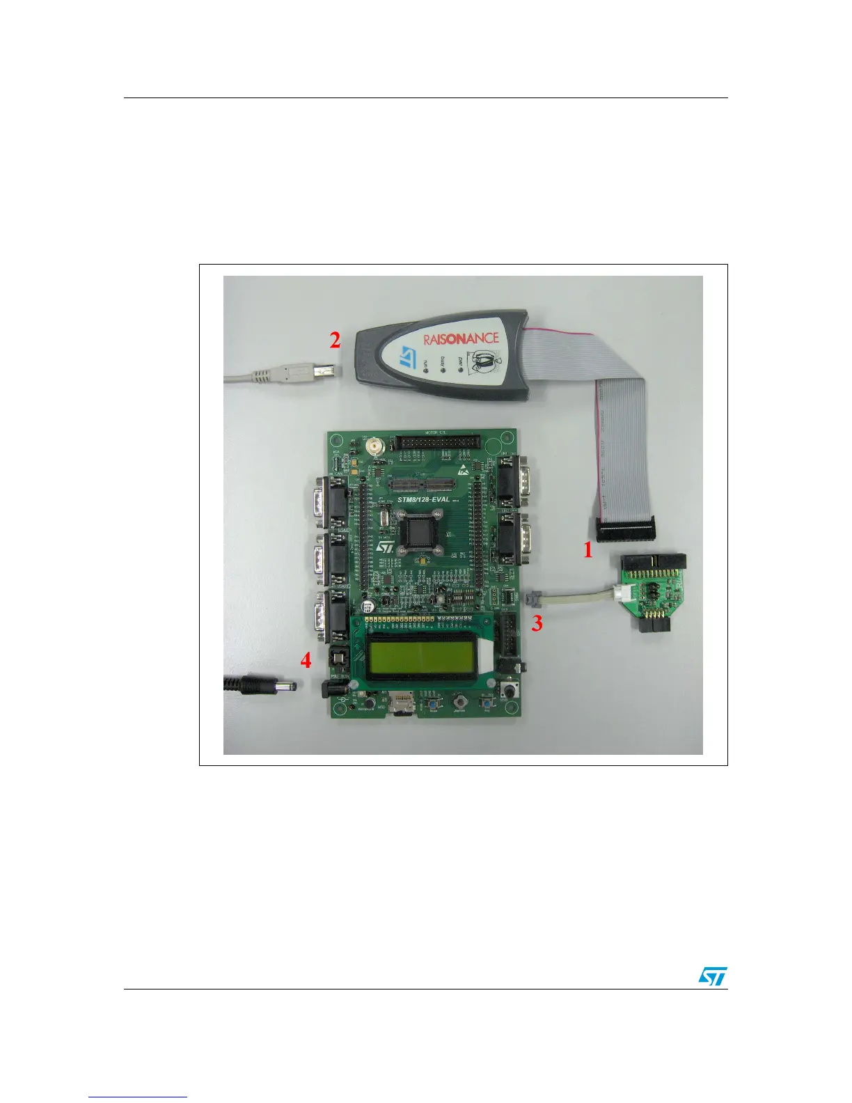
Figure 25. Connecting the debug instrument to the STM8 evaluation board
Caution: On the Rlink ICC/SWIM adapter board, the “SWIM” jumper must be set.
If there is no pull-up on the application SWIM line, the “ADAPT” jumper is also set.
In any case, “PW-5V” and “12MHz” jumpers must not be set.

 Loading...


