Do you have a question about the stellar labs 5521 and is the answer not in the manual?
Explains NOTICE, WARNING, and DANGER signals used throughout the manual for safety.
Provides contact details including phone number and email for technical assistance.
Details the crane's performance, dimensions, weight, and operational parameters.
Visual guide for safe lifting capacities at various boom extensions and angles.
Prerequisites and general advice for mounting the crane on a suitable vehicle.
Information on installer responsibilities regarding vehicle safety standards.
Recommended torque values for various bolts and screws used in installation.
Step-by-step instructions for physically attaching the crane to a vehicle.
Schematics for various remote control kits including CDT Boost and 12V versions.
Diagram illustrating the electrical connections for the crane's operation.
Schematics for the CDT and 12V CDT hydraulic kits.
Diagrams and parts lists for standard and alternate valve banks.
Instructions for connecting hydraulic lines and filling the system with oil.
Overview of the crane's hydraulic circuit functions and flow.
Reference chart for identifying hydraulic fitting seals and O-ring sizes.
Steps to prepare the crane and vehicle for stability testing.
Method for conducting tests and calculating revised load capacities.
Explanation of the indicator used to ensure safe side-to-side leveling.
Lists safety, warning, and identification decals with their positions on the crane.
Exploded view and parts list for the crane's base assembly.
Exploded view and parts list for the gear bearing mechanism.
Exploded view and parts list for the mast component.
Exploded view and parts list for the main boom.
Exploded view of the first type of extension boom.
Parts list for the first type of extension boom.
Exploded view of the second type of extension boom.
Parts list for the second type of extension boom.
Exploded view and parts list for the main hydraulic cylinder.
Exploded view and parts list for the 2-hydraulic extension cylinder.
Exploded view and parts list for the 1-hydraulic/1-manual extension cylinder.
Exploded view and parts list for the cable and hook system.
Exploded view and parts list for the power unit.
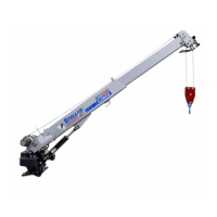
| Brand | stellar labs |
|---|---|
| Model | 5521 |
| Category | Construction Equipment |
| Language | English |