EasyManuals Logo

StepperOnline RS485 User Manual

StepperOnline RS485
63 pages
To Next Page IconTo Next Page
To Previous Page IconTo Previous Page
Page #16 background imageLoading...
Page #16 background image
Modbus RS485 Stepper Drive User Manual
9
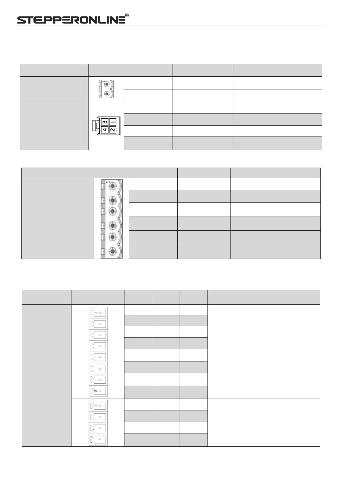
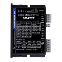
3.3.2 CN1 &CN2 Input Power Connector
DM556RS
Name
Pic
PIN
Signal
Description
CN1
1
VDC
24V- 48V
2
GND
GND
CN2
4
A+
Motor phase A+
3
B+
Motor phase B+
2
A-
Motor phase A-
1
B-
Motor phase B-
DM882RS
Name
Pic
PIN
Signal
Description
CN1&CN2
1
A+
Motor phase A+
2
B+
Motor phase B+
3
A-
Motor phase A-
4
B-
Motor phase B-
5
AC
18-80VAC or 24-100VDC;
No polarity
6
AC
Note: When the user uses an AC transformer to supply power, be sure to use an isolation transformer to prevent
electric shock or burn out the computer
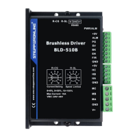
3.3.3 CN3-I/O Signals Connector
Name
Pic
PIN
Signal
I/O
Description
CN4
1
DI1
I
Configurable Single-ended Digital
Inputs DI1-DI7, 12V - 24V.
DI1 is enabling signal default, DI2-DI7
are GPIOs
2
DI2
I
3
DI3
I
4
DI4
I
5
DI5
I
6
DI6
I
7
DI7
I
8
COMI
I
9
DO1
O
Configurable Single-ended Outputs
Signals DO1-DO3 (common-cathode or
common-anode),
Max. 24V/100mA, GPIOs.
10
DO2
O
11
DO3
O
12
COMO
O

Table of Contents

Questions and Answers:

Question and Answer IconNeed help?

Do you have a question about the StepperOnline RS485 and is the answer not in the manual?

StepperOnline RS485 Specifications

General IconGeneral
BrandStepperOnline
ModelRS485
CategoryDC Drives
LanguageEnglish

Related product manuals