Modbus RS485 Stepper Drive User Manual
3.4 I/O Connection
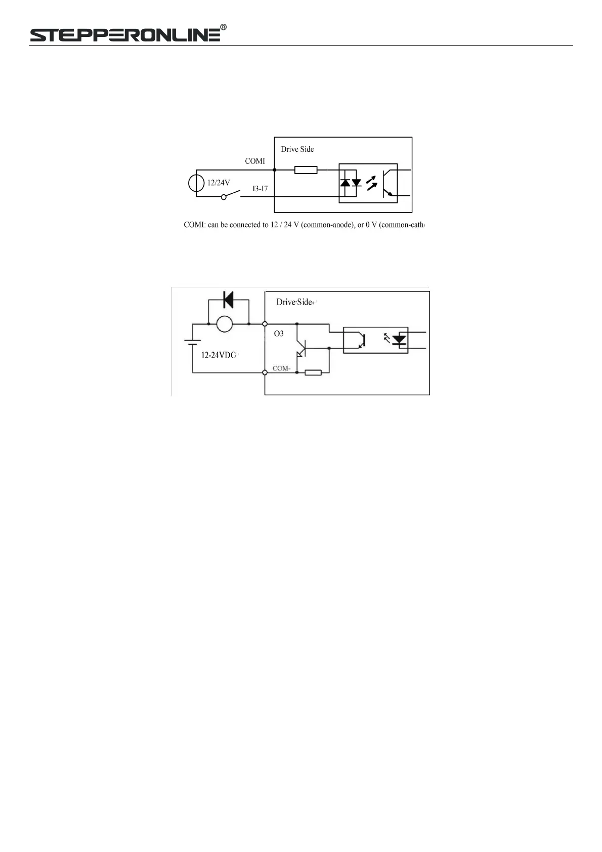
3.4.1 Digital Inputs
The connections of input signals are as below:
Figure 3.3: Input Interface Connection
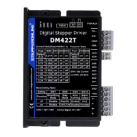
3.4.2 Digital Output
Figure 3.4: Output Interface Wiring
Note: (1) The power supply (12-24VDC) above is provided by user, and if the polarity of power supply is reversed, it
will damage the drive.
(2) Digital output is OC output with the maximum capacity of 100mA/24V (recommended 50mA/24V), the provided
power supply should be under 30V (recommended 24V), otherwise it will cause damage to the drive.
3.4.3 Brake Output
Use PC software (from STEPPERONLINE or Controller or PLC vendor) to configure this output as a BRAKE
CONTROL output. In this case, this signal can be used for automatic brake control while system power failure. It is
recommended to connect a fly-wheel diode in parallel to a 24VDC relay and brake coil connection. Refer to the
following figure for brake connection.