EasyManuals Logo

StepperOnline RS485 User Manual

StepperOnline RS485
63 pages
To Next Page IconTo Next Page
To Previous Page IconTo Previous Page
Page #17 background imageLoading...
Page #17 background image
Modbus RS485 Stepper Drive User Manual
10
Note:(1) DI1 is normally closed, default by Enable signal. It means the motor is locked shaft after the driver powered
on.
(2) When using Brake output signals, you need to connect a relay and a diode
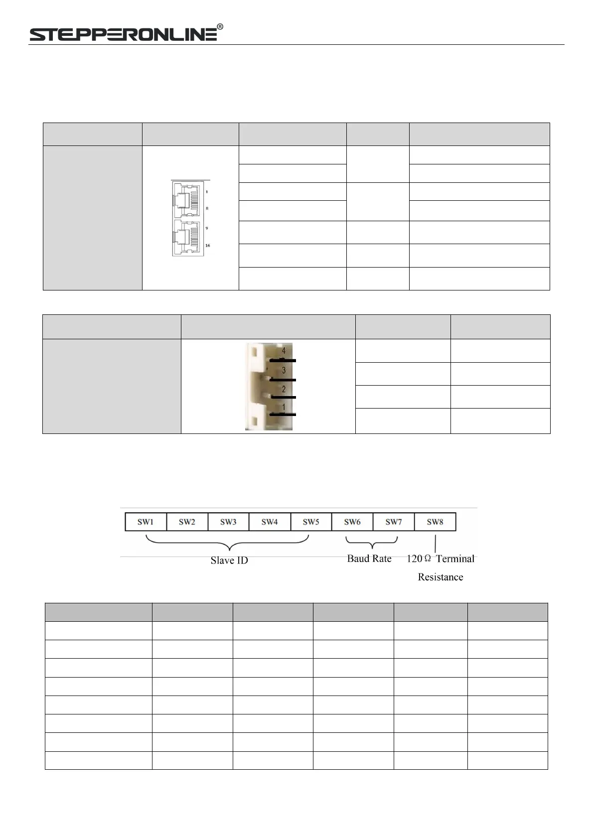
3.3.4 CN4-RS485 Communication Connector
Name
Pic
PIN
Signal
Description
CN5
1
RS485+
RS485 TxD+
9
RS485 RxD+
2
RS485-
RS485 TxD-
10
RS485 RxD-
5, 6, 13, 14
GND
GND
7, 8, 15, 163, 4, 11, 12
NC
Received
Connector cover
PE
Shield GND
3.3.6 CN5-RS232 Tuning Port
Name
Pic
PIN
Signal
CN6
1
NC
2
TxD
3
GND
4
RxD
3.3.8 DIP Switches
The DMRS series drives use an 8-bit DIP switched to set Salve ID (also called Site Alias), Baud Rate and Terminal
Resistance, they are shown as below:
(1) Slave ID: SW1-SW5 (off=1, on=0)
Slave ID
SW1
SW2
SW3
SW4
SW5
1 (default)
on
on
on
on
on
1 (factory)
off
on
on
on
on
2
on
off
on
on
on
3
off
off
on
on
on
4
on
on
off
on
on
5
off
on
off
on
on
6
on
off
off
on
on
7
off
off
off
on
on

Table of Contents

Questions and Answers:

Question and Answer IconNeed help?

Do you have a question about the StepperOnline RS485 and is the answer not in the manual?

StepperOnline RS485 Specifications

General IconGeneral
BrandStepperOnline
ModelRS485
CategoryDC Drives
LanguageEnglish

Related product manuals