INSTALLATION
Mounting
26 | WPF basic www.stiebel-eltron.com
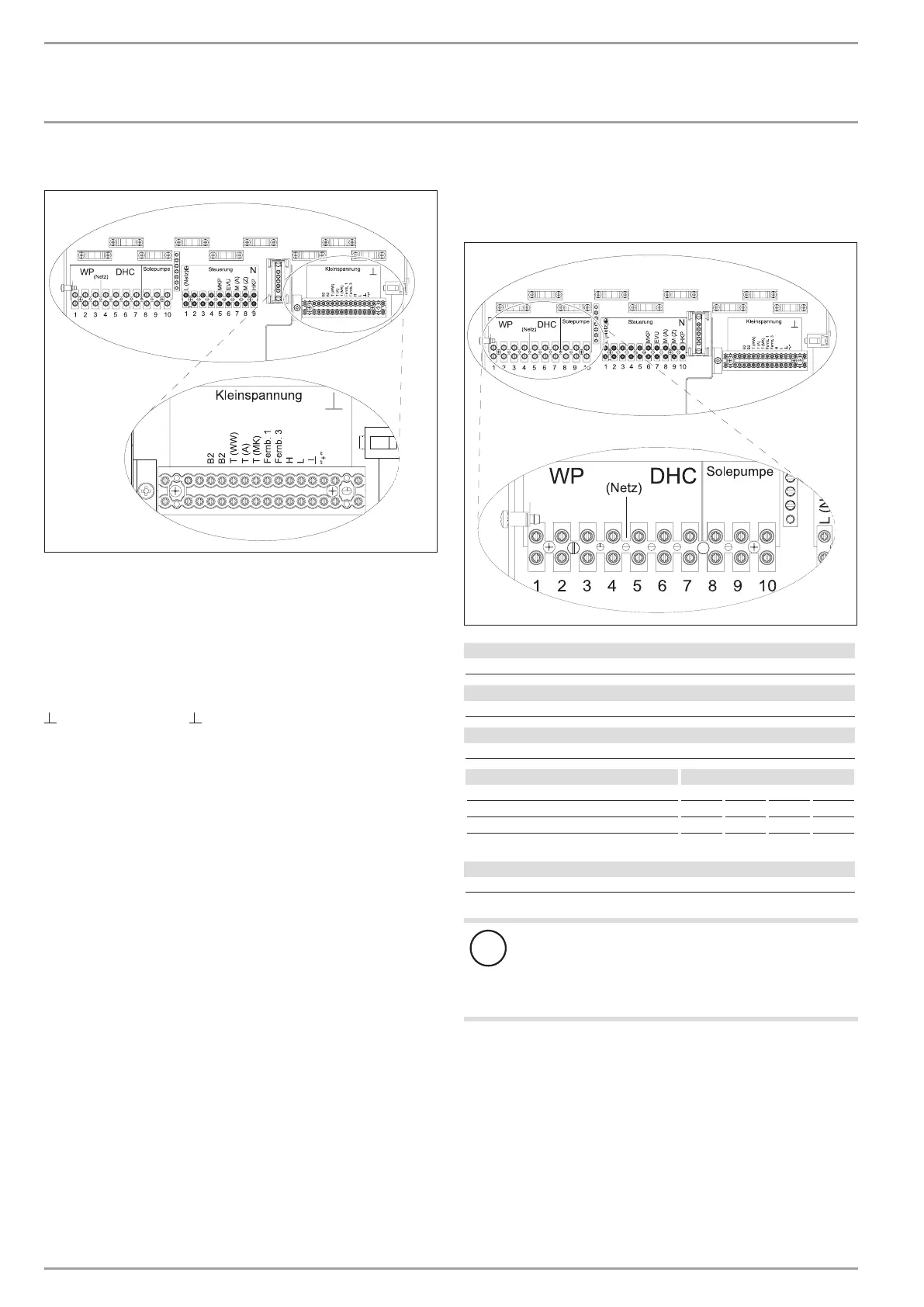
Connections X2: Low voltage
L1 L2 L3 N L1 L2 L3 L1’ L2’ L3’
ON
KS
Kühlen
1 2 3 4 5 6 7 8 9 10 11 12 13
B1
B1
1 2 3 4 5 6 7 8 9 10 11 12 13
B1
B1
26�03�01�1581
B1 Temperature sensor heat pump flow
B2 Temperature sensor heat pump return
T (WW) DHW temperature sensor and earth
T(A) Outside temperature sensor and earth
T(MK) Mixer circuit temperature sensor and earth
Fernb. 1 Remote control 1
Fernb. 3 Remote control 3
H BUS high
L BUS low
BUS ground
“ + “ BUS “ + “
10.12.2 Electrical connection WPF S basic (single-phase)
Connection X3: Heat pump, electric booster heater and brine
pump
L N R RC L L’ N L N PE
S
ON
KS
Kühlen
1 2 3 4 5 6 7 8 9 10 11 12 13
B1
B1
26�03�01�1611
Heat pump power supply (compressor)
L, N, PE
Heat pump with WPAB power supply
R, RC, N, PE
DHC power supply (electric booster heater)
L, L´, N, PE
Connected load Terminal assignment
3.0 kW L N PE
3.2 kW L´ N PE
6.2 kW L L´ N PE
Brine pump power supply
L, N, PE
!
Material losses
When a single phase brine pump is connected, protect
the heat pump and the DHC only via one common RCD.
If no electric emergency/booster heater is connected, N
must be tapped from X25 for the brine pump.
After connecting all electrical cables, refit and seal the cover over
the mains terminal strip.