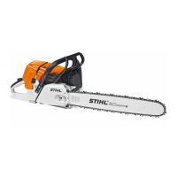
105MS 461, MS 461-R
.
Component Ohmmeter connection
(use either test lead)
Resistance Ω If faulty
Lead 1 Lead 2 Spec. Actual Cause Remedy
Generator Yellow wire
with
terminal pin
on wire
from
handlebar
heating
element
0.85 0.6 - 1.1 Generator OK
Red wire
with
terminal
socket on
wire from
handlebar
heating
element
0.65 0.5 - 0.8 Generator OK
- Break in wire,
generator damaged
Install new
generator
0 Short circuit –
damaged insulation
Install new
generator
G = Generator
1 = Rear handle
2 = Handlebar
3 = Heater switch
4 = Thermostatic switch
5 = Heating element (carburetor)
6 = yellow wire
7 = red wire
3443RA470 TG
G
1 4
5
2
3
67
Circuit diagram of handle and carburetor heating system

 Loading...