26 MS 461, MS 461-R
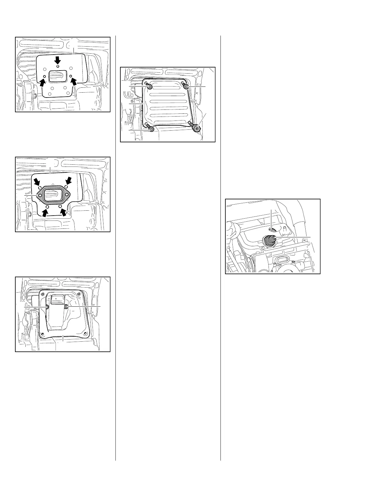
: Line up heat shield (1) with pegs
(arrows) on cylinder exhaust port
and place it in position.
: Line up the muffler gasket (1) on
the pegs (arrows) of the heat
shield (2) and place it in position.
: Carefully place the muffler (1) in
position.
: Coat screws (2) with
threadlocking adhesive, b 15
: Check the position of the heat
shield and gasket and fit the
screws (2).
3443RA014 TG
1
1
3443RA015 TG
2
3443RA016 TG
2
2
1
: Insert and tighten down the
screws (2) firmly.
– Fit a new gasket.
Special screw (4) is fitted only on
the rescue saw. Screw (3) is used at
the bottom left and right on all other
models and coated with
threadlocking adhesive.
: Coat screws (2 and 3) and
special screw (4) with
threadlocking adhesive, b 15
: Fit top casing (1), insert the
screws (2 and 3), screw (4) and
tighten them down firmly.
– On rescue saw, fit the guard
plate.
6.2 Leakage Test
Defective oil seals and gaskets or
cracks in castings are the usual
causes of leaks. Such faults allow
supplementary air to enter the
engine and upset the fuel-air
mixture.
This makes adjustment of the
prescribed idle speed difficult, if not
impossible.
1
2
3443RA019 TG
3
2
4
Moreover, the transition from idle
speed to part or full throttle is not
smooth.
Oil seals tend to fail when subjected
to a vacuum. Therefore, always
perform the vacuum test first and
then the pressure test.
The engine can be checked
thoroughly for leaks with the pump
0000 850 1300.
6.2.1 Preparations
– Remove the filter cover and air
baffle.
– Remove the shroud, b 6.4
– Pull off the boot and unscrew the
spark plug.
– Set the piston to top dead center.
This can be checked through the
spark plug hole.
– Remove the decompression
valve, b 6.9
: Fit the plug (1) 1122 025 2200
and tighten it down firmly.
: Fit the spark plug (2) and tighten
it down firmly.
– Remove the top casing and
loosen the muffler screws, b 6.1
3443RA062 TG
1
2

 Loading...


