94 MS 461, MS 461-R
Installing
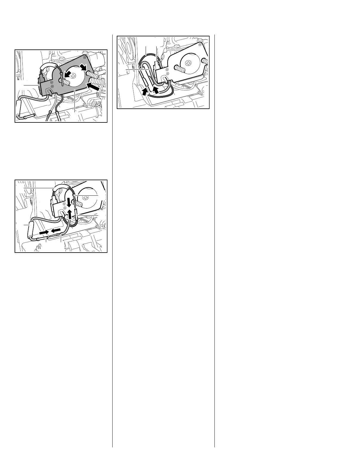
The gasket must be in place.
: Fit the heating element (1) over
the studs (arrows) so that the
thermocouple (2) faces inwards.
Insulating tubes (1) must be fitted.
: Connect the pins (2) and
sockets (3) and center the
insulating tubes (1) over the
connectors.
3443RA487 TG
2
1
3443RA488 TG
2
3
3
2
1
1
: Push the insulating tube with
connector of black wire (1) and
insulating tube with connector of
green / yellow wire (2) into the
center of the guides (arrows).
The green / yellow wire (2) must be
run between the guide and
thermocouple (3).
– Install the baffle plate, b 12.4
– Reassemble all other parts in the
reverse sequence.
13.1.3 Thermostatic Switch
The thermostatic switch is an
electronic component that cannot
be tested directly. Its operation can
be checked with the aid of the
troubleshooting chart, b 13.2
The thermostatic switch and the
heating element form a single unit. If
the switch is faulty, the heating
element must be replaced.
Removal and installation are
described in the chapter on
"Heating Element", b 13.1.2
– Check operation
3443RA489 TG
1
2
3

 Loading...


