9
Synchronization with distributed clocks
ID 441896.05
WE KEEP THINGS MOVING
Operation manual
44
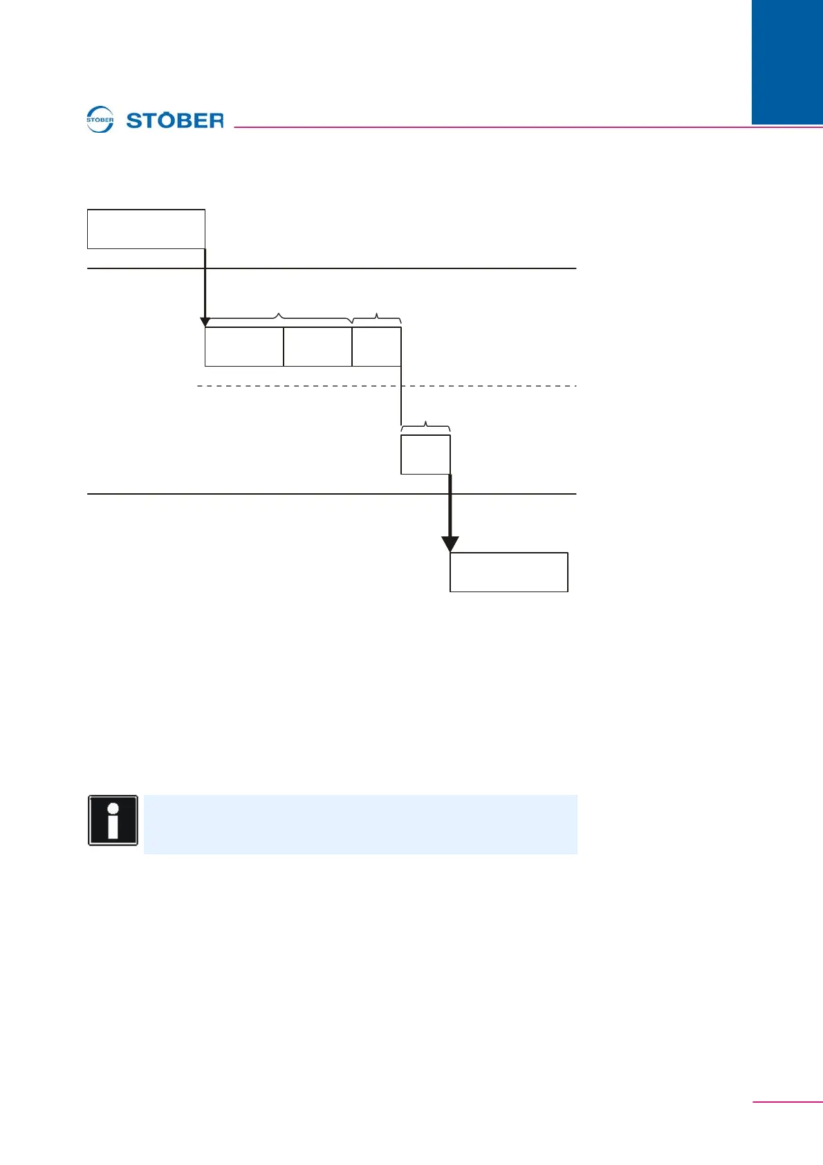
Fig. 9-1 Effect of different times on the SYNC0 signal
The runtime system of the inverter is synchronized to the SYNC0 signal with a
device-internal software PLL (G90 = 1:active). After synchronization, the
technology task A150 on the inverter is synchronous with the SYNC0 signal.
Permissible cycle times for the SYNC0 signal are whole-number multiples of the
technology task A150. Remember that the inverter will not change to the Safe-
Operational state when SYNC0 signal cycle times are inadmissible.
Example:
A150 = 5: 2 ms -> Permissible cycle times of SYNC0: 2 ms, 4 ms, 6 ms, 8 ms, etc.
Monitoring synchronization
Monitoring of the synchronization is activated by setting the parameter A260 = 1.
When monitoring is active, the inverter checks to determine whether the
EtherCAT telegram arrives within a specified time period in relation to the SYNC0
signal. If there was too much jitter, the error counter is incremented in A261.2. The
error counter is reset when the inverter is turned on.
Information
PLL jitter on the inverter can only be taken into account on the master
(e.g., via the Slave User Shift Time).
EtherCAT
runtime
PLC
task
10 %
reserve
U
U
on slave
Same time for
all stations
Time can be
set differently
Transmit data
to the slaves
Slave accepts data
Generate data on Master
Master User
Shift Time
Master
Shift Time
Inverter
task