183
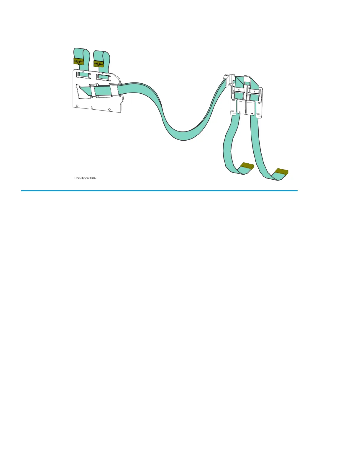
9. Remove the head ribbon cables and cable brackets from the printer. See Figure 7-25.
Figure 7-25: Head Ribbon Cables and Brackets
Installing the Head Ribbon Cables
1. Install the rear ribbon cable bracket to cutouts at the back, top of the printer frame.
See Figure 7-24.
2. Using a 3 mm hex wrench install the mounting screws (3) to fasten the front ribbon cable bracket
to the back of the toggle assembly. See Figure 7-23.
3. Connect the rear head ribbon cable connectors (2) to the I/O board (J6 and J7). See Figure 7-22.
4. Connect the front head ribbon cable connectors (2) to the material and support heads. See
Figure 7-22.
5. Install the rear panel. See “Installing the Rear Panel” on page 170.
6. Close the top cover.