of connection to the vehicle power supply according to the power cable
requirements of the product.
(1) Required tool: multimeter.
(2) Selection of power supply connection position
When the vehicle is shut down, use a test pencil to detect whether the circuit is live.
If it is live, it is judged as a constant power supply, and then measure the voltage.
When the vehicle is shut down and is in ACC position or ignition state, use a test
pencil to detect whether the circuit is live. If it is electrically neutral in shutdown
state, and is live in ACC position or ignition state, it is judged as an ACC power
cable, and then measure the voltage.
(3) Voltage measurement of power supply connection
Constant power supply: When the vehicle is shut down, use a multimeter to
measure whether the voltage of the constant power supply cable is about 24V. If the
voltage of multiple cables is about 24V in shutdown state, select the cable with
higher current as the constant power supply connection cable.
ACC:When the vehicle is in ACC position or ignition state, use a multimeter to
measure whether the voltage is about 24V. If the voltage is 0 in shutdown state and
about 24V in ACC position or ignition state, select the cable as the ACC power
supply connection cable.
*Note: During power supply connection, first conduct measurement at the positive
and negative terminals of the power supply with a multimeter, to avoid wrong
connection.
2.5 Connection of Necessary Signal Cables
Where required, the following signal cables must also be connected to enable the
intelligent assisted driving functions of AD Plus:
(1) Vehicle speed pulse cable or CAN data cable - to obtain accurate vehicle speed
data;
(2) Left and right steering signal cables - to obtain left and right steering
information of vehicle;
(3) Brake signal cable - to obtain vehicle braking information.
Please consult the maintenance engineer of the vehicle discipline for specific
position of vehicle speed pulse cable/CAN data cable. Generally, the left and right
steering signal cables and the brake signal cable are arranged on the fuse board
below the steering wheel or below the front passenger dashboard, and measurement
for these cables can be conducted using a multimeter.
*Note: If the measured signal is a pulse signal, the source of left steering/right
steering/brake signal shall be set as pulse on the setting interface of the main unit; if
the measured signal is a continuous high or low level signal, the source of left
steering/right steering/brake signal shall be set as level on the setting interface of the
main unit.
3. Preparation of List of Installation Materials and Tools
3.1 Inspection as per Packing List
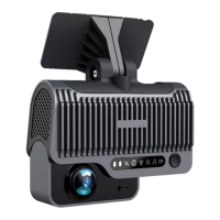
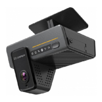
After unpacking the product, please confirm whether the DVR is intact and whether
the accessories are complete.