main unit.
4.6.3 Wiring
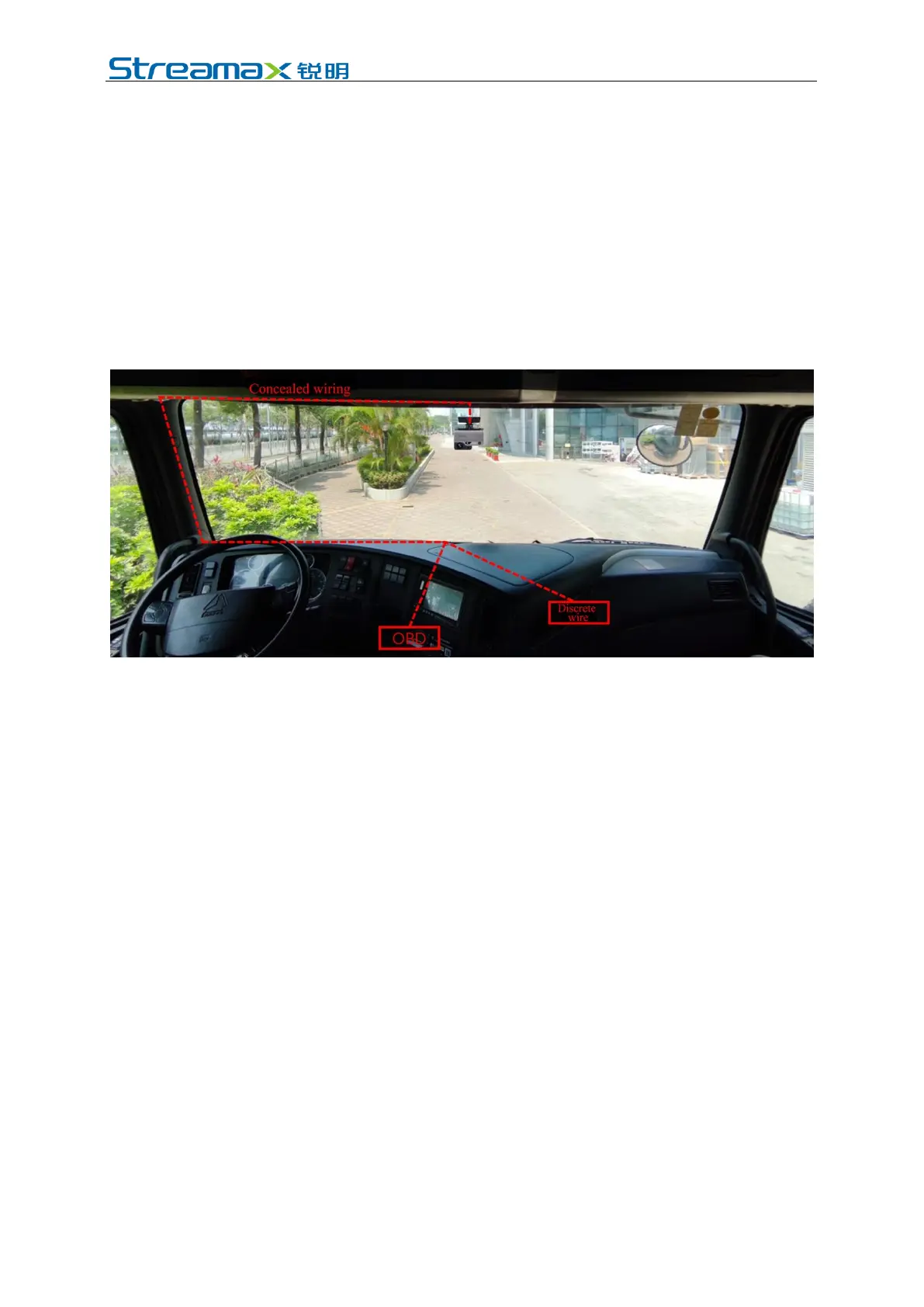
Upon the completion of connection of main cables according to the schematic
diagram of system connection, as well as power supply connection and connection
of signal cables, arrange these cables using a crow plate according to the diagram
below and conceal them in the interior trim panel or the panel of the dashboard (i.e.
concealed wiring).
If DMS camera or BSD camera (optional) is required, the wire length of DMS
camera and BSD camera can be reserved for wiring at the above-mentioned position.
(1) If the mode of power supply connection through OBD interface or discrete
wire is adopted, the wiring mode is as follows:
Since ADPlus has a power supply box with built-in turning-on/off control strategy,
it is necessary to fix the power supply box at a certain position on the vehicle.
Attention should be paid to the following items when the fixing position is selected:
1. Close to OBD interface or power ports of discrete wire
2. Horizontal surface mounting
3. Not interfered with other components
4. Away from vibrating and jittering positions, such as trumps and motors
5. Hidden positions preferred
Since different vehicle models have different OBD interface positions, the
corresponding wiring and the fixed position of the power supply box vary. Here, we
recommend two installation positions for the power supply box. You can also fix
the power box in other positions according to the actual vehicle model.
Fixed position 1 of power supply box:
Remove the side trim in the driving seat area, tear 3M cellophane wrapping the
power supply box and fix it on the left or right side-trim, please see below: