*This user manual describes the full functionality including the recording function and may not be applicable if the PVR
software has not yet been installed.
2.0 YOUR RECEIVER
2.1 Default PIN: 0000
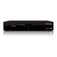
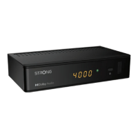
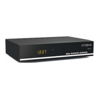
2.2 Front panel
Fig. 1
1. USB: To connect a USB storage device for multimedia functions or
software updates
2. LED display: Shows channel number in operation and time in Standby mode
3. Power button: Switch the receiver to Standby or On.
4. Standby indicator: Shows power state of the receiver
Green LED - receiver is switched on
Red LED - receiver is in standby mode
5. MENU Open the main menu.
6. Remote control sensor:
Receives the signal from the remote control
7. CH-/CH+: To change channels without using the remote control.
Navigation functions in menu mode.
8. VOL-/VOL+ Decrease/Increase audio volume. Navigation functions in menu
mode.
9. OK Confirm settings.
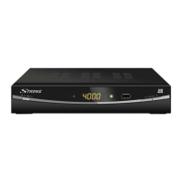
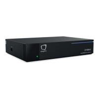
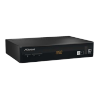
2.3 Rear panel
Fig. 2
1. Ethernet To connect to a network switch, router or modem
2. SAT IN To connect to the LNB of your satellite dish for reception of
satellite broadcast signal
3. SAT OUT To loop through the satellite signal to a second receiver
4. S/PDIF coaxial To connect to a digital or home cinema audio amplifier
5. USB For connection of USB device for Multimedia use
6. HDMI To connect to the HDMI input of your TV using a good quality
HDMI cable.
7. TV SCART To connect to TV using a SCART cable
8. Power cord The receiver requires a mains voltage of 100~240V AC 50~60Hz
(auto selecting). Please check the local power conditions before
connecting the receiver to the power supply.
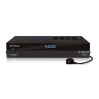
2.4 Remote Control
Fig. 3
1. q Switches the receiver ON/Standby
2. ! To mute the audio outputs
3. RED Flexible functions in OSD menu and Teletext
5