Assembly & Installation
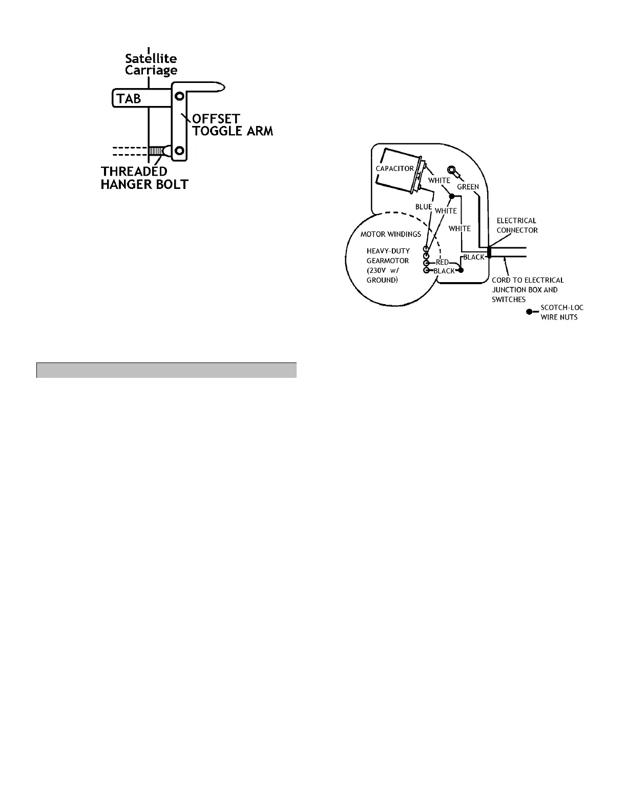
Figure 26 - Satellite-Carriage End of Reversing Mechanism
53 Bolt threaded hanger bolt (now screwed into
reversing rod) to toggle arm using a 5/16”
shoulder bolt and 1/4” locking nut. Ensure
reversing mechanism is still in centered
position; toggle arm should still be parallel to
edge of carriage. Figure 26.
54 Tighten all 3 shoulder bolts using a 5/32” hex
(Allen) wrench and a 7/16” wrench.
55 Ensure reversing mechanism can move freely by
shifting it from one locked position to the other.
IX. Wiring Gearmotor on Center Hanger
For part numbers and descriptions of parts
referenced in this section, see parts assembly
manual, page 53.
56 Run black 18 ga. 3-wire cord from primary
carriage junction box underneath crosstube and
tie bar and tie-strap cord to cord support strap.
57 Run cord along cord hanger and down side of
center hanger, securing cord using provided
black zip ties.
58 Remove curved cover with Sukup logo on front
of gearmotor junction box using 5/16” wrench.
Save 1/4" screws.
59 Insert 3/8” electrical connector from hardware
sack into hole on side of gearmotor junction
box. Figure 27.
60 Tighten metal fastening ring inside of box.
61 Thread 3-wire cord through electrical connector,
providing a drip loop in cord by motor. Secure 3-
wire cord by lightly tightening connector screws
using screwdriver.
61.1 Note: At this point, there will be 4 wires
from gearmotor and 3 wires from 3-wire
cord inside gearmotor junction box.
62 Connect loose, short white wire with female
spade (located in plastic sack on junction box
wire) to terminal of capacitor that is included
inside gearmotor junction box. Figure 27.
62.1 Note: Sack with white wire should come
attached to carriage junction box and also
includes yellow wire nuts.
62.2 Note: In steps 62-66, ensure wires and wire
nuts are connected tightly so they do not
vibrate out of place during use of machine.
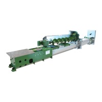
Figure 27 - Gearmotor Junction Box Wiring Diagram
63 Connect blue wire with female spade from
gearmotor to terminal on opposite side of
capacitor. Figure 27.
64 Strip back 1/2” of rubber insulation on white,
red, and black wires from gearmotor using wire
stripper.
65 Using yellow wire nut from attached part sack,
connect:
White wire from 3-wire cord
White wire from gearmotor
White wire from step 62. Figure 27.
66 Using yellow wire nut from attached part sack,
connect:
Black wire from 3-wire cord
Black wire from gearmotor
Red wire from gearmotor. Figure 27.
67 Secure green ground wire from 3-wire cord
under the ground screw inside junction box.
67.1 Note: All wires should now be connected
somewhere.
68 Place capacitor and all wires back into
gearmotor junction box.
69 Replace cover from step 58 on gearmotor using
reserved 1/4” screws and 5/16” wrench.
69.1 Note: Ensure wires are not pinched
between gearmotor junction box and box
cover before tightening cover down.