Assembly & Installation
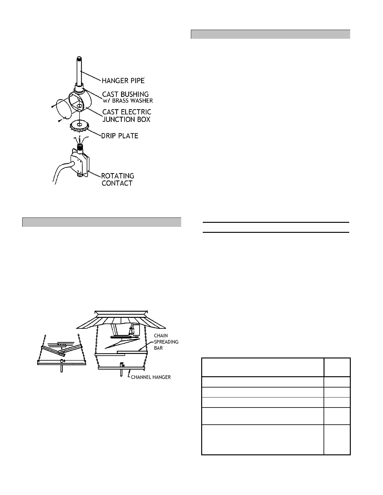
88 After machine is raised in bin, place drip plate
over threaded end of rotating contact so plate
opens downward. Figure 34.
Figure 34 - Rotating Contact Installation
89 Tightly thread rotating contact into bottom of cast
electric junction box on center hanger. Figure 34.
XIV. Installing Optional Spreader-Bar Kit
For part numbers and descriptions of parts
referenced in this section, see parts assembly
manual, page 53.
On narrow hatch openings, it may be necessary to
spread hanger chains to provide clearance for grain
spreader fin. The following instructions detail
installation of Sukup Manufacturing Co.’s optional
spreader bar kit (Comp# A5635).
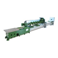
90 Determine clearance needed and place one bolt
in proper hole on spreading bar.
Figure 35 - Placement and Installation of Spreader Bar
91 Place slotted ends of spreading bar on chain as
shown and force chains apart by pushing bar
straight. Figure 35.
91.1 Note: Ensure spreading bar is far enough
below grain spreading fins to avoid fins hitting
bar while in position of maximum incline.
92 Place second bolt in matching holes on
spreading bar and tighten both bolts.
93 Ensure crosstube remains level after spreading
chains; re-level if needed.
XV. Preparing Down Augers
For part numbers and descriptions of parts referenced
in this section, see parts assembly manual, page 53.
Down augers must be 3” to 5” above floor or any
unloading equipment that would serve as an
obstruction at bin bottom.
DISCLAIMER: Use of down augers longer than 20’
will void warranty on stirring machine. Damage to
other components as a result of using down augers
over 20’ will not be the responsibility of Sukup
Manufacturing Co.
Sukup Manufacturing Co. makes no warranty,
express or implied, with respect to down augers
longer than 20’, including, without limitation, any
warranty of merchantability and warranty of fitness
for a particular purpose. The following calculations
will help determine down auger cut length.
Down Auger Cut Length
Depending upon your bin setup, you may need 2
different lengths of down augers for proper clear-
ance and operation. Use the following formulas to
calculate your required down auger length(s).
Note: Final cut length tolerance is + or -1.0".
CALCULATING DOWN AUGER LENGTH
DA = L +(plus) H - (minus) Clearance
L: Measure from the top of the track rail to floor
of bin.
H: For bins up to 40': 7.5"
For bins 40' and up: 8.0"
Clearance: The clearance is the distance from bin
floor to bottom of auger taking into account any
obstructions such as a sweep. Recommended
clearance to any obstruction or floor is 3 to 5 inches.
Note: The far outside auger or stationary auger
MAY need to be shorter to clear the sweep
drive wheel. Figure 36.
Following are dimensions of typical Sukup products
to aid in calculating down auger length.
REFERENCE DIMENSIONS OF SUKUP PRODUCTS
Product and Relational Dimensions
Needed for Accurate Calculation
6" and 8" Sukup powered sweeps
Sukup powered sweep drive wheel
Height from cement floor to top of metal
floor with standard 13.25" floor supports
Top of bin sheet to top of rail on pre-
punched, non-commercial Sukup bins
(Use if track is to be installed on existing
horizontal bin sheet bolts.)
(Examples of calculations shown on next page)